Stator for rotating electrical machine

A technology for rotating electrical machines and stators, applied in the manufacture of motor generators, electrical components, electromechanical devices, etc., can solve the problem of inability to cool the ends of the coils, and achieve the effect of improving the cooling effect and increasing the contact area.

Active Publication Date: 2014-01-22
DENSO CORP
View PDF5 Cites 20 Cited by
  • Summary
  • Abstract
  • Description
  • Claims
  • Application Information

AI Technical Summary

Problems solved by technology

[0007] However, in the above-mentioned conventional stator winding, the coil ends of the stator winding have the same axial height, so when the cooling medium is supplied from the radially ou

Method used


Image

  • Stator for rotating electrical machine
  • Stator for rotating electrical machine
  • Stator for rotating electrical machine

Examples


Embodiment approach 1

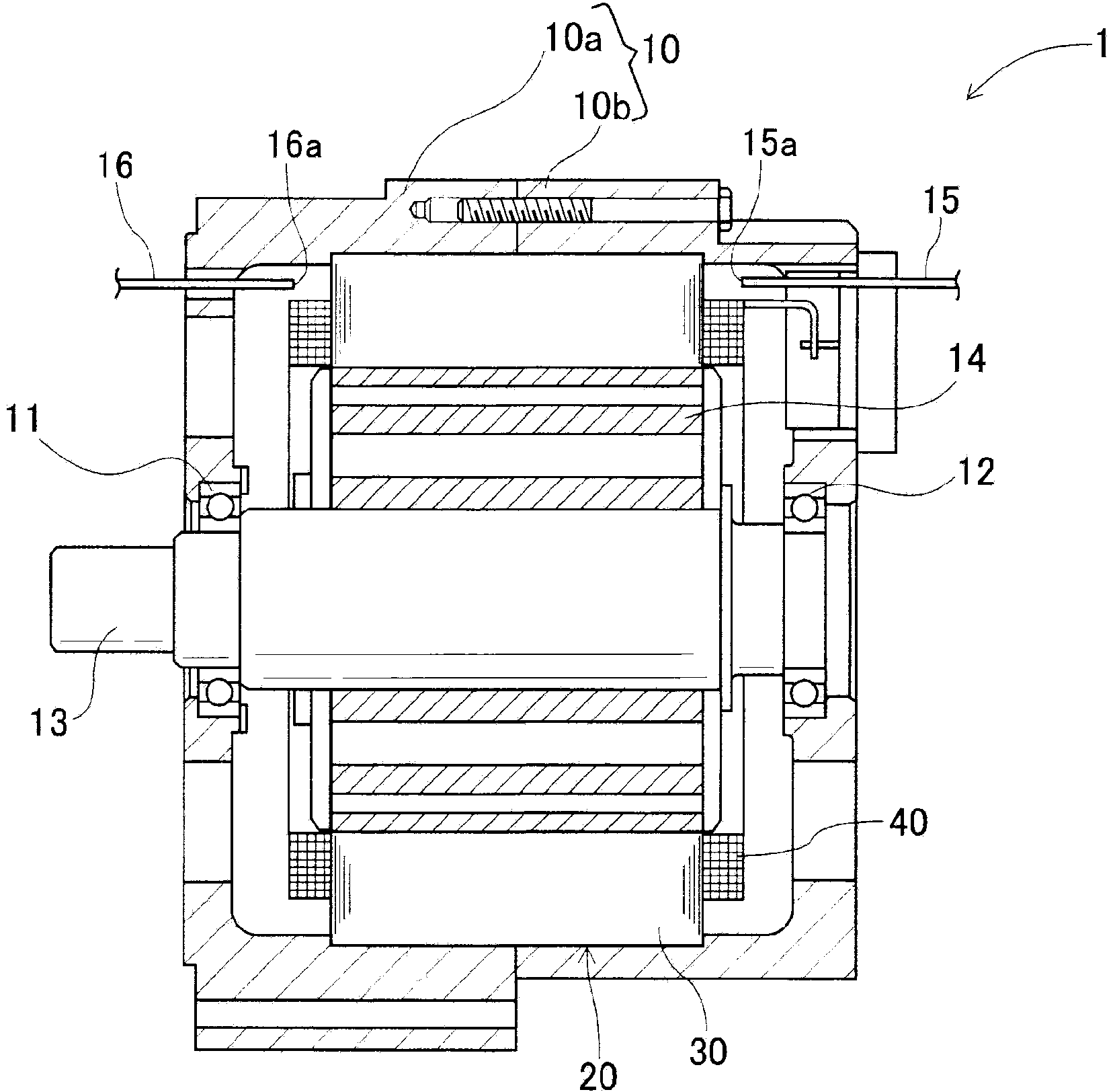
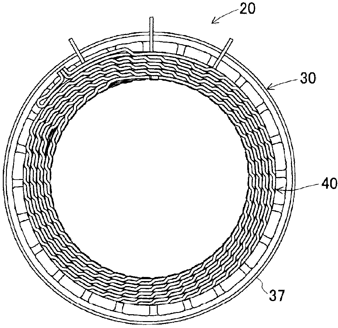
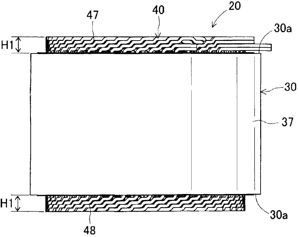
[0058] The stator of the present embodiment is mounted on a rotating electrical machine used as a vehicle generator. figure 1 It is an axial cross-sectional view schematically showing the structure of a rotating electrical machine equipped with a stator according to the present embodiment. like figure 1 As shown, the rotating electric machine 1 of the present embodiment includes a housing 10 formed by joining a pair of substantially bottomed cylindrical housing members 10A and 10B at openings, and is supported on the housing 10 via bearings 11 and 12 . A rotatable rotary shaft 13 , a rotor 14 fixed to the rotary shaft 13 , and a stator 20 fixed to the casing 10 surround the rotor 14 within the casing 10 .

[0059] In addition, the rotary electric machine 1 is provided with a refrigerant supply unit including a pair of refrigerant pipes 15 and 16 for supplying a cooling medium for cooling to the stator winding 40 of the stator 20 . Refrigerant lines 15 and 16 communicate betw...

Embodiment approach 2

[0094] Figure 11 It is a perspective view seen from the conductor segment insertion side of the stator of Embodiment 2. Figure 12 It is a perspective view seen from the conductor segment welding side of the stator of Embodiment 2. Figure 13 It is explanatory drawing which shows the state which inserted the conductor segment into the slot of the stator core in Embodiment 2.

[0095] The stator 120 of this embodiment is the same as that of the first embodiment, and is also mounted on the rotary electric machine 1 used as a power generator for a vehicle. Figure 11 ~ Figure 13 As shown, the difference between the stator winding 140 and the first embodiment is that a plurality of substantially U-shaped conductor segments 150 are assembled in the stator core 130 and then connected in a predetermined state.

[0096] The stator 120 of the present embodiment includes an annular stator core 130 and a stator winding 140 formed by combining a pair of linear portions, a turning porti...


PUM


Abstract

A stator (20) is provided with an annular stator core (30) having a plurality of slots (31) positioned at predetermined intervals in the circumferential direction, and stator windings (40) comprising a plurality of conductor wires (50) assembled in the stator core (30). Each conductor wire (50) has a plurality of slot housing sections (51) housed in the slots (31) of the stator core (30), and a plurality of turns (52) for connecting adjoining slot housings (51) outside of the slots (31). The stator windings (40) have first and second coil elements (47, 48) that protrude axially outward from both ends of the stator core (30) in the axial direction. At each coil end, the turns (52) of the plurality of conductor wires (50) are laminated in the radial direction of the stator core (30), and the height (h1) in the axial direction of the turns (52) is set so as to become gradually higher toward the outside in the radial direction from the inside in the radial direction.

Description

technical field [0001] The present invention relates to a stator of a rotating electric machine used as a motor or a generator in a vehicle, for example. Background technique [0002] Conventionally, there is known a stator of a rotating electrical machine comprising an annular stator core having a plurality of slots arranged at predetermined intervals in the circumferential direction, and a plurality of conductive wires assembled to the stator core. of the stator winding. In addition, each lead wire has a plurality of slot accommodation portions accommodated in slots of the stator core, and a turning portion connecting adjacent slot accommodation portions to each other outside the slots. [0003] In addition, each conducting wire forming the stator winding may be constituted by one wave-shaped continuous conducting wire having a plurality of slot receiving portions and a plurality of turning portions. Alternatively, it is possible to use a plurality of conductor segments ...

Claims


Application Information

Patent Timeline
IPC IPC(8): H02K3/04H02K9/19
CPCH02K3/12H02K15/0031H02K15/0081H02K2213/03H02K3/24H02K3/14H02K9/00H02K3/04H02K3/46
Inventor 盛昭夫秋本明人石塚敦朗
Owner DENSO CORP
Why Eureka
Try Eureka