
Bypass valve with hyperboloid structure

A hyperboloid, bypass valve technology, used in valve devices, internal combustion piston engines, engine components, etc., can solve the problems of severe wear of parts, large movement space, increased clearance in all directions, etc., to enhance structural strength and wear resistance. The effect of increasing the contact area and reducing the sports wear

Inactive Publication Date: 2014-01-29
WUXI CUMMINS TURBO TECH
View PDF4 Cites 4 Cited by
  • Summary
  • Abstract
  • Description
  • Claims
  • Application Information

AI Technical Summary

Problems solved by technology

[0005] Due to the large internal axial and radial gaps, the structure is easy to move during the movement, resulting in a large movement space for the structure and insufficient structural stability. It is difficult to control the position of the valve plate during the movement. attitude; the usual bypass valve design, in the environment of large impact inertia and high-frequency movement, due to the action of movement and rotation, it is easy to produce surface shear and excessive local stress, resulting in severe wear between its parts , which in turn leads to an increase in the gap in all directions, a sharp increase in the amount of movement, and a worse motion state of the bypass valve. Such a vicious cycle will eventually lead to symptoms such as the valve cover is not tight, air leakage, function failure, bypass valve falls off, and the engine is weak.
Therefore, the ordinary bypass valve design can no longer meet the application requirements of the gas machine family

Method used


Image

  • Bypass valve with hyperboloid structure
  • Bypass valve with hyperboloid structure
  • Bypass valve with hyperboloid structure

Examples


Embodiment Construction

[0021]

[0022] Below the present invention will be further described in conjunction with the embodiment in the accompanying drawing:

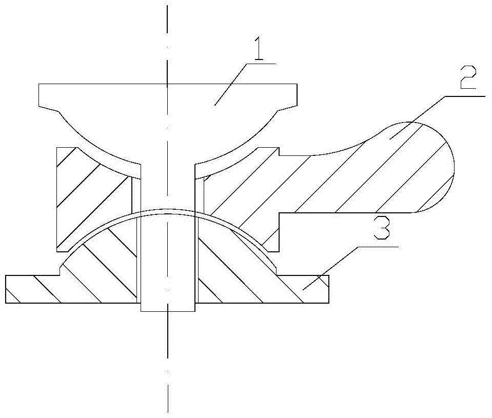
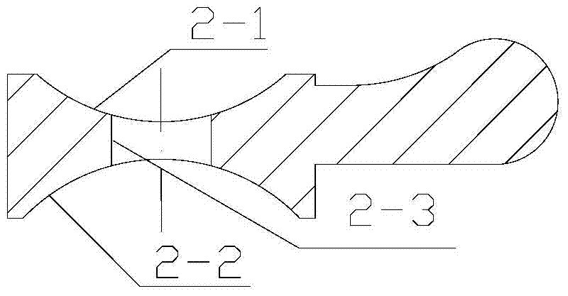
[0023] Such as Figure 1-Figure 4 As shown, it includes: a T-shaped pin 1, a hyperboloid rocker arm 2, and a valve plate 3 with a curved surface.

[0024] A hyperboloid structure bypass valve of the present invention includes a T-shaped pin 1, a hyperboloid rocker arm 2 and a valve plate 3 with a curved surface; the hyperboloid rocker arm 2 and the valve plate 3 with a curved surface pass through the T-shaped pin 1 connected into one.

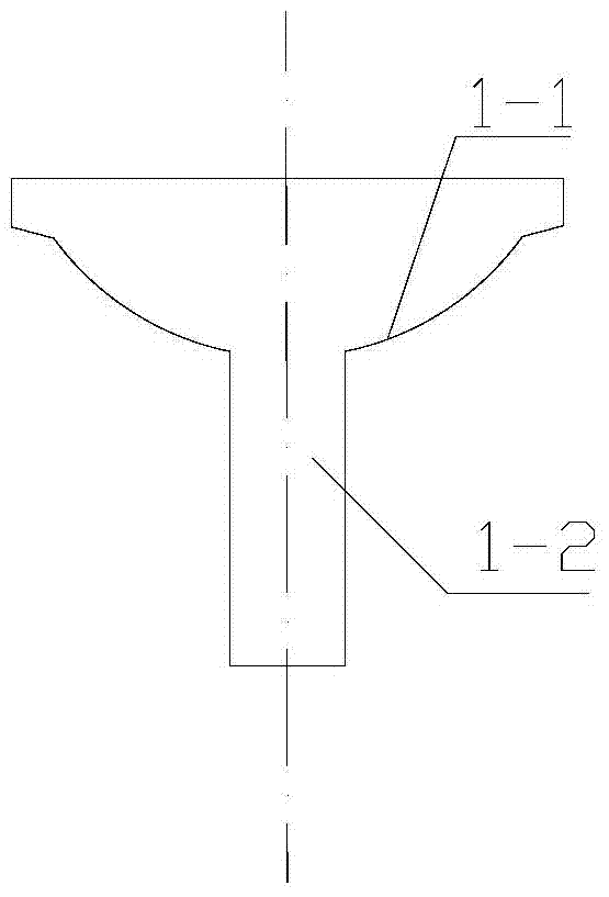
[0025] The T-shaped pin is composed of an upper spherical pin head 1-1 connected with a lower cylindrical rod 1-2. Among them, the upper spherical pin head 1-1 is the main stress feature, and the design of the spherical surface effectively improves the force distribution of the contact surface and decomposes the wear of the contact point; the cylindrical rod 1-2 part is in the entire bypass valve structure. ...


PUM


Abstract

The invention relates to a bypass valve with a hyperboloid structure. The bypass valve comprises a T-shaped pin, a hyperboloid rocker and a hook-faced valve plate, and the hyperboloid rocker and the hook-faced valve are integrally connected through the T-shaped pin. The T-shaped pin is composed of a spherical pin head on the upper portion and a cylindrical rod on the lower portion. A hook face and a spherical face are respectively arranged on the hyperboloid rocker. A hook face and a plane structure are respectively arranged on the valve plate, and the spherical face of the valve plate and the spherical face of the hyperboloid rocker form a spherical-face motion pair. The bypass valve is simple, compact and reasonable in structure; acting force in the process of running is reasonably optimized, so that motion abrasion among parts can be reduced; contact area in the rotation is enlarged, so that severe abrasion caused by single-point contact is avoided; impacting force is effectively distributed, so that shearing abrasion during turning on and off is reduced; the contact area of rotary motion is enlarged, so that structural strength and abrasion resistance are enhanced, and service life is prolonged.

Description

technical field [0001] The invention relates to a hyperboloid structure bypass valve, which is used for waste gas bypass valves of engine turbochargers, especially for gas engines. Background technique [0002] With the development of engine technology, the implementation of emission standards, the improvement of social environmental protection awareness, and the development of new energy sources, natural gas has been more and more widely used. This requires that the turbo shell of the supercharger has sufficient flow capacity, and can provide enough energy for the pressure wheel in the low speed section to meet the sufficient engine intake pressure requirements. Therefore, the bypass valve on the turbine shell has a decisive contribution when facing such a demand. [0003] The requirement for the bypass volume of the supercharger applied to the gas engine is much greater than that of the diesel engine, which requires the bypass valve to have a larger flow capacity, that is...

Claims


Application Information

Patent Timeline
IPC IPC(8): F02B39/00F02B37/18F16K51/00
CPCY02T10/144Y02T10/12
Inventor 陈志秋陈伟
Owner WUXI CUMMINS TURBO TECH
Learn More