
Printing device of SLM equipment

A printing device and equipment technology, which is applied in the direction of improving process efficiency, additive processing, and energy efficiency, can solve problems such as difficult to meet axisymmetric, improve the mechanical properties of materials and structures, improve the quality of scraping powder, and use convenient effect

Pending Publication Date: 2020-12-18
ZHEJIANG YIDONG TECH CO LTD
View PDF0 Cites 0 Cited by
  • Summary
  • Abstract
  • Description
  • Claims
  • Application Information

AI Technical Summary

Problems solved by technology

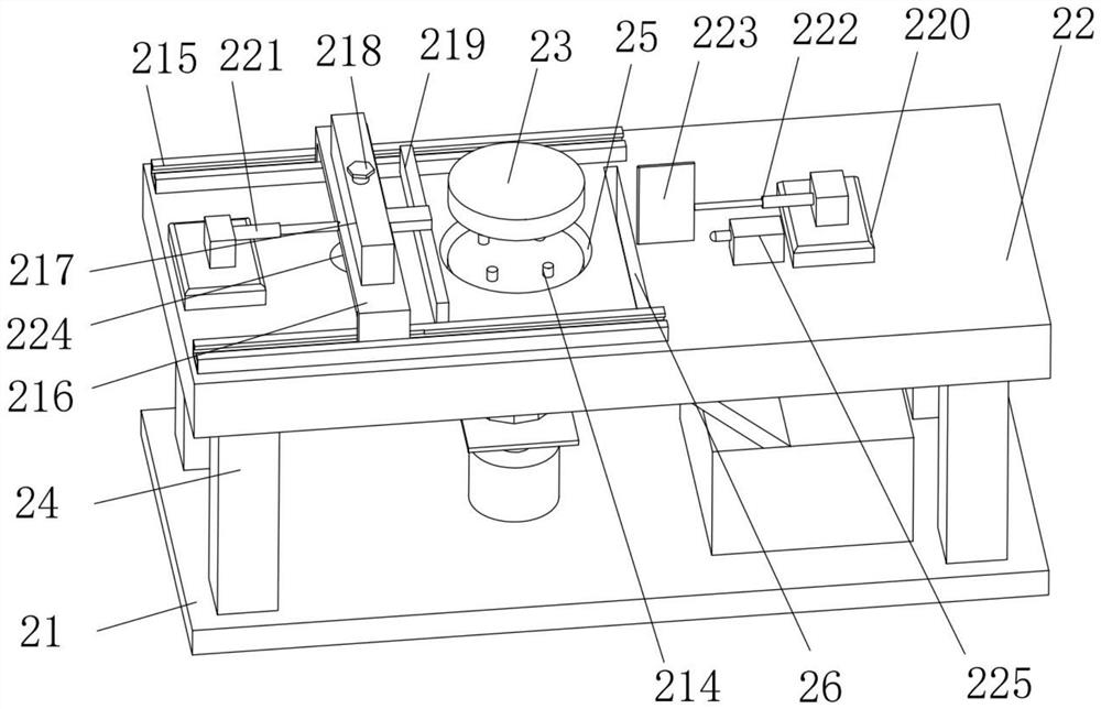
The printing device of the SLM equipment of the present invention solves the problem that it is difficult to meet the axis symmetry of the rotating parts in the prior art and requires the staff to clean up the excess powder; in addition, the powder scraping device of the present invention improves The uniformity of powder scraping, at the same time, the height of the powder scraping blade can be adjusted according to the actual situation, so as to realize the precise adjustment of the thickness of the powder layer

Method used


Image

  • Printing device of SLM equipment
  • Printing device of SLM equipment
  • Printing device of SLM equipment

Examples


Embodiment 1

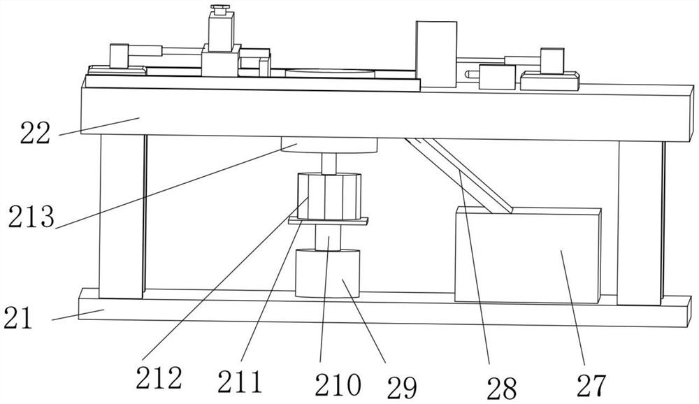
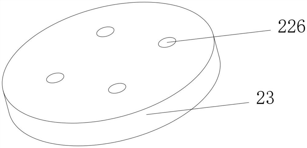
[0048] Such as Figures 1 to 7 As shown, a printing device of SLM equipment, including a substrate, a worktable, and a printing round table;

[0049] The four corners of the upper surface of the substrate are fixedly connected with support columns, the workbench is fixedly connected to the upper surface of the support columns, a circular through hole is opened in the middle of the upper surface of the workbench, and the workbench The surface is located on the right side of the circular through hole, and a material leakage hole is opened. The right side of the upper surface of the substrate is fixedly connected with a collection box. A hydraulic cylinder is fixedly connected in the middle of the surface, the output end of the hydraulic cylinder is fixedly connected with a hydraulic rod, and the upper end of the hydraulic rod is fixedly connected with a loading plate, and a motor is fixedly installed on the upper surface of the loading plate, and the motor The output end of the...

Embodiment 2

[0052] Such as Figures 1 to 7 As shown, a printing device of SLM equipment includes a substrate, a worktable, and a printing round table. Support columns are fixedly connected to the four corners of the upper surface of the substrate, and the workbench is fixedly connected to the upper surface of the support column. The upper surface of the workbench There is a circular through hole in the middle of the surface, and a material leakage hole is opened on the upper surface of the workbench on the right side of the circular through hole. The middle of the upper surface of the substrate is fixedly connected with a hydraulic cylinder, the output end of the hydraulic cylinder is fixedly connected with a hydraulic rod, the upper end of the hydraulic rod is fixedly connected with a loading plate, the upper surface of the loading plate is fixedly installed with a motor, and the output of the motor The end is fixedly connected with a cylindrical shaft, and the printing round table is se...


PUM


Abstract

The invention discloses a printing device of SLM equipment. The printing device comprises a base plate, a workbench and a printing circular truncated cone. Supporting columns are fixedly connected tothe four corners of the upper surface of the base plate, the workbench is fixedly connected to the upper surfaces of the supporting columns, a circular through hole is formed in the middle of the upper surface of the workbench, a material leaking hole is formed in the upper surface of the workbench and located at the right side of the circular through hole, and a material collecting box is fixedlyconnected to the right side of the upper surface of the base plate; the material leaking hole is communicated with a material collecting box through a material guiding hopper, and a hydraulic cylinder is fixedly connected to the middle of the upper surface of the base plate; and a powder scraping device comprises a mounting frame and a powder scraping knife, multiple sets of corresponding slidinggrooves are formed in the left side and the right side of the mounting frame in the horizontal direction, and adjusting plates are arranged in the sliding grooves in a sliding manner. According to the printing device of the SLM equipment, the problems that in the prior art, when a rotating part is machined, axial symmetry is difficult to meet, and workers need to clean redundant powder are solved; and the uniformity of powder scraping is improved in a multi-time powder scraping manner, and meanwhile accurate adjustment of the thickness of a powder layer can be achieved.

Description

technical field [0001] The invention relates to the technical field of SLM equipment, in particular to a printing device of the SLM equipment. Background technique [0002] Selective laser melting (SLM) metal 3D printing technology (Selective laser melting, SLM) uses a precise focus spot to quickly melt the pre-laid layers of metal powder, and can almost directly obtain functional parts with arbitrary shapes and complete metallurgical bonding. The density can reach nearly 100%. It is a rapid prototyping technology with great development prospects, especially in aerospace, medical, automobile, mold and other fields, which has extremely important application prospects. There is a powder spreading process in the SLM process, that is, after the powder is sent to the powder bed by the powder feeding mechanism, it is paved by the powder spreading device. This process directly affects the printing result. [0003] 3D printing is a kind of rapid prototyping technology, also known a...

Claims


Application Information

Patent Timeline
IPC IPC(8): B22F3/105B33Y30/00
CPCB33Y30/00Y02P10/25
Inventor 韩品连
Owner ZHEJIANG YIDONG TECH CO LTD
Learn More