Locating and clamping mechanism of screen printing machine

A technology of screen printing machine and clamping mechanism, which is applied in the direction of screen printing machine, printing machine, rotary printing machine, etc., can solve the problem of increasing the overall installation error of the clamping mechanism, increasing the installation error of the clamping mechanism, and θ angle and distance increase, to achieve the effect of shortening the maintenance cycle, reducing the difficulty of maintenance, and reducing the fragmentation rate

Active Publication Date: 2014-01-15
HUNAN RED SUN PHOTOELECTRICITY SCI & TECH
View PDF5 Cites 0 Cited by
  • Summary
  • Abstract
  • Description
  • Claims
  • Application Information

AI Technical Summary

Problems solved by technology

Under the action of the spring tension to the left of the pillar 5 and the gravity of the clamping mechanism itself, even if the machining accuracy of the mounting hole of the bearing 3 is the limit G7 of the tolerance zone preferred by the national standard, the error caused by the downward movement of the claw sleeve only reaches 0.4 mm, and the processing cost is high and difficult. If the accuracy does not meet the requirements, the installation error of the clamping mechanism will increase; according to the structural geometric characteristics, the rest errors are far smaller in magnitude than the processing error of the bearing 3 installation hole, but still Tend to increase the overall installation error of the clamping mechanism
[0005] The structural wear during operation is mainly reflected in the wear of the mounting hole of the bearing 3. After a period of continuous operation, under the alternating cyclic action of the spring tension, the gravity of the clamping mechanism itself and the reaction force of the silicon wafer, the angle θ and the distance h increase, and the positioning Performance keeps getting worse
[0006] In addition, due to the inevitable slurry leakage during the use of the equipment, the bearing 7 in this structure that ensures the free rotation of the claw sleeve is easily polluted by the slurry, resulting in bearing damage, the claw sleeve 2 cannot rotate, and the fragmentation rate increases

Method used


Image

  • Locating and clamping mechanism of screen printing machine
  • Locating and clamping mechanism of screen printing machine
  • Locating and clamping mechanism of screen printing machine

Examples


Embodiment Construction

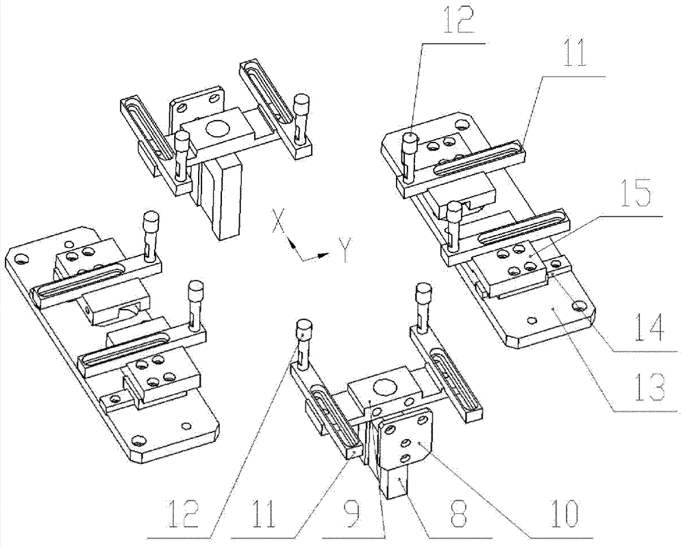
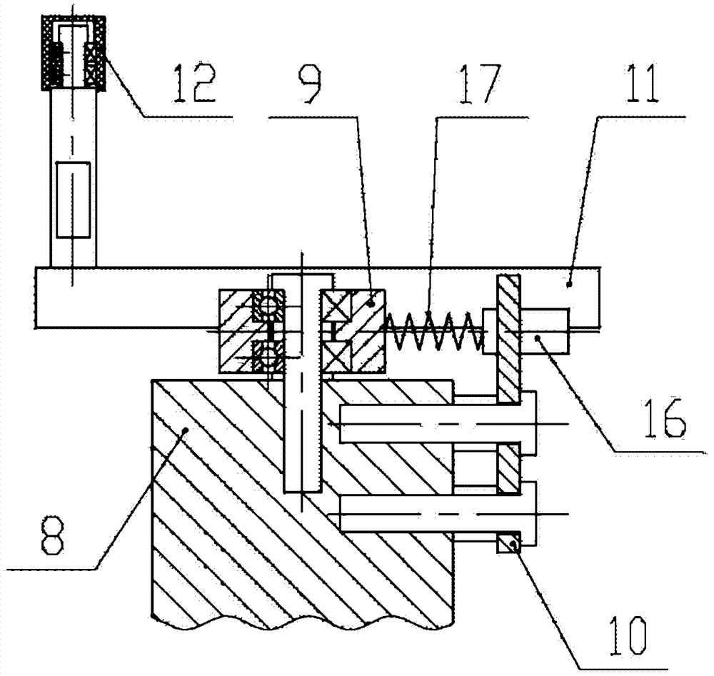
[0038] A positioning and clamping mechanism for a screen printing machine, such as figure 2 and image 3 As shown, the clamping mechanism in the X direction has a driving base 8, which is driven by the positioning transmission mechanism of the screen printing machine, and the whole reciprocates in the X direction. The self-balancing rotating base 9 is connected with the drive base 8 through short-head screws, two bearings and gaskets, so that the self-balancing rotating base 9 can rotate around the short-head screws. The spring baffle plate 10 is connected with the drive base 8 through two spacers, and is equipped with two convex head screws 16 at the same time. The end acts on the self-balancing rotating base 9 through the tension spring 17, and the elastic force of the tensioning spring 17 is changed by adjusting the convex head screw 16, so that the self-balancing rotating base 9 is in a balanced position. The adjusting rod 11 is fixed in the slot of the self-balancing r...


PUM


Abstract

The invention discloses a locating and clamping mechanism of a screen printing machine, which belongs to the field of solar silicon cell production equipment. In order to solve the problem that traditional clamping mechanism relatively highly affects location accuracy, repeatability, stability and fragment rate of the screen printing machine, the locating and clamping mechanism of the screen printing machine disclosed by the invention comprises a pawl sleeve assembly, at least two groups of the clamping mechanisms located in an X direction and at least two groups of the clamping mechanisms located in a Y direction. The clamping mechanisms in the X direction and the clamping mechanisms in the Y direction locate the solar cell silicon wafer from four directions and eight functional points. By adopting the device of the invention, movement precision of the locating and clamping mechanism is improved, influence from the structural abrasion to the operating performance is reduced, the location accuracy, the reliability as well as printing quality are improved, the fragment rate is reduced, maintenance period is shortened, the maintenance difficulty is reduced and the like; and the locating and clamping mechanism is particularly suitable to be applied on cell printing equipment.

Description

technical field [0001] The invention relates to solar silicon cell production equipment, in particular to a positioning and clamping mechanism for a screen printing machine. Background technique [0002] The structural characteristics of the positioning and clamping mechanism are the key factors affecting the positioning accuracy, repeatability and stability of the screen printing machine. At present, when the positioning and clamping mechanism of the screen printing machine is debugged or after running for a period of time, the positioning accuracy cannot meet the process requirements, and the fragmentation rate is relatively high. The above-mentioned situation will be caused when the motion accuracy of the positioning and clamping mechanism deviates from the design target, and the entire clamping mechanism needs to be replaced at this time. [0003] figure 1 A schematic structural view of a positioning and clamping mechanism of a screen printing machine according to the ...

Claims


Application Information

Patent Timeline
Patent Type & Authority Patents(China)
IPC IPC(8): B41F15/18
Inventor 吴迪邓斌万喜新贾京英
Owner HUNAN RED SUN PHOTOELECTRICITY SCI & TECH
Why Eureka
Try Eureka