Drying tunnel achieving reheating and pressurizing of circulating air

A secondary heating and circulating air technology, applied in lighting and heating equipment, drying, drying machines, etc., can solve the problems of difficult preheating recovery and high energy consumption, achieve compact structure, uniform air volume, and improve drying efficiency Effect

Active Publication Date: 2014-01-29
烟台珈群高效节能设备有限公司
View PDF7 Cites 2 Cited by
  • Summary
  • Abstract
  • Description
  • Claims
  • Application Information

AI Technical Summary

Problems solved by technology

[0003] In addition, the air inlet and moisture outlet of the existing drying tunnel are respectively set at both ends of the drying tunnel, which makes it difficult to preheat and recover, and the energy consumption is high

Method used


Image

  • Drying tunnel achieving reheating and pressurizing of circulating air

Examples


Embodiment Construction

[0013] The present invention will be further described below in conjunction with the accompanying drawings and examples.

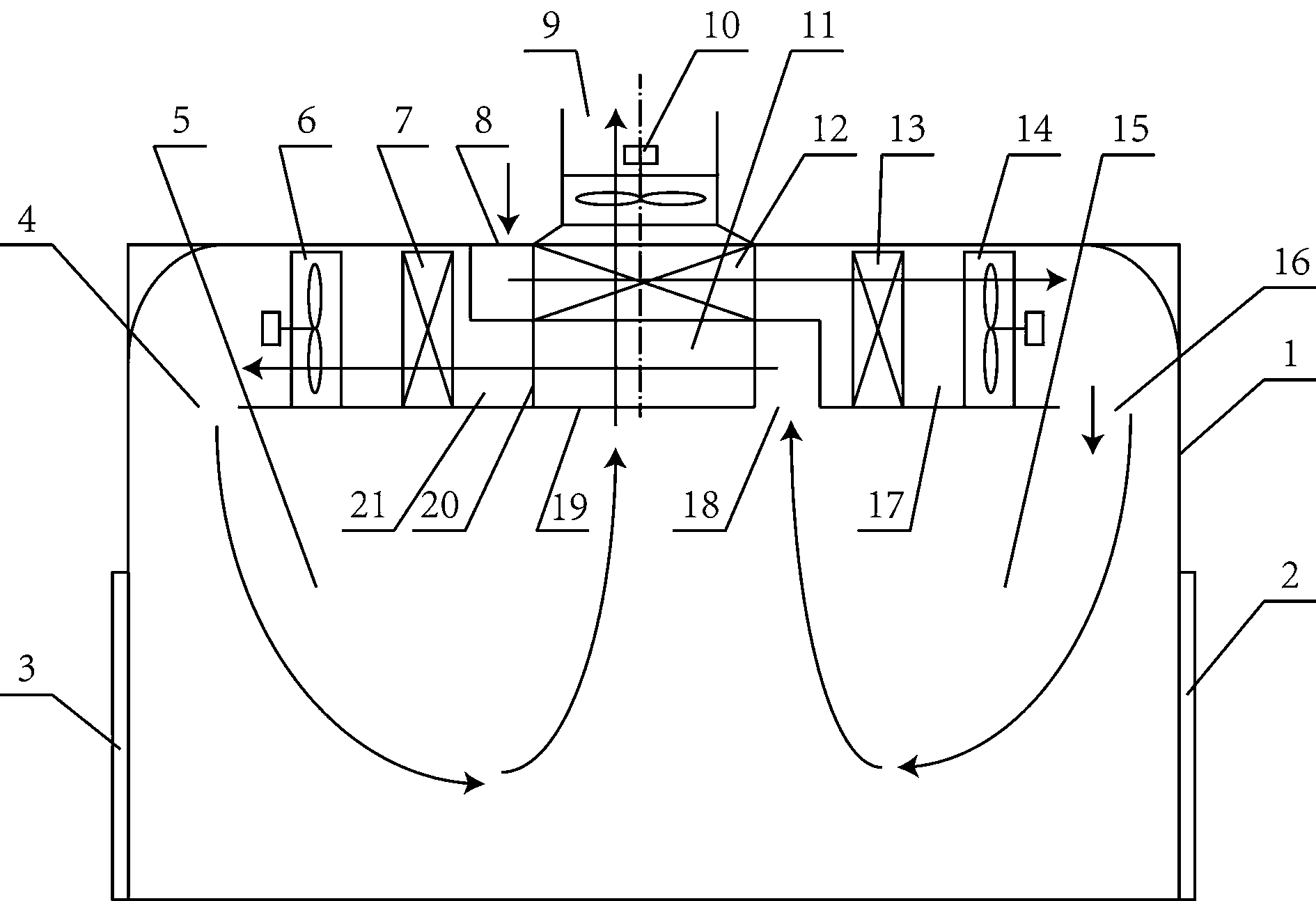
[0014] Such as figure 1 , this embodiment includes an outer casing 1 of the drying tunnel with an inlet door 3 at one end and an outlet door 2 at the other end. A first fan 14 , a first heater 13 , a moisture discharge channel 20 , a second heater 7 and a second fan 6 are sequentially arranged in the upper space inside the outer casing 1 of the drying tunnel. Wherein, the positions of the first blower 14 and the first heater 13 can be exchanged, and the positions of the second heater 7 and the second blower 6 can be exchanged.

[0015] The lower space inside the shell 1 of the drying tunnel is a drying area, which is composed of a first drying area 15 and a second drying area 5 which are connected. Wherein, the lower end of the tide discharge passage 20 has a tide discharge outlet 19, and the upper end has a tide outlet 9, and a tide discharge fan 10 is ...


PUM


Abstract

The invention discloses a drying tunnel achieving reheating and pressurizing of circulating air. The air outlet of a fresh air heating channel (17) is a first air inlet (16), the air inlet end of a circulating air heating channel (21) is a return air opening (18) at the upper end of the middle portion of a drying area, the air outlet of the circulating air heating channel (21) is a second air inlet (4), the return air opening (18) is connected with the air inlet end of a second heater (7) through a gap bridge channel (11), and the trends of a moisture removal channel (20) and the gap bridge channel (11) intersects; the first air inlet (16) and the second air inlet (4) are close to the feed end and the discharge end respectively. The design guarantees that air volume inside the drying channel, especially air volume in relatively long drying channel, is uniform, the temperature fluctuation range is smaller, the moisture content of air for extracting moisture is maximized, not only is the drying efficiency improved and product quality guaranteed, but also the effects of energy saving and emission reduction are achieved.

Description

technical field [0001] The invention relates to a drying tunnel for heating materials with hot air. Background technique [0002] The existing drying tunnel generally adopts the structure of one end for air inlet and the other end for air outlet. A heater is installed at the air inlet end to heat the air at room temperature. The hot air takes away the moisture of the material and is discharged from the air outlet end under the action of the fan. In the case of a long drying tunnel, the air temperature at the air inlet end is higher and the humidity is lower, while the temperature near the air outlet end is lower and the humidity is higher. The temperature and humidity gradient in the drying tunnel is larger. Large, the attenuation of the air flow velocity in the drying tunnel is relatively serious. On the one hand, the drying efficiency is low. On the other hand, because the materials near the air outlet are in a state of low temperature and high humidity for a long time, es...

Claims


Application Information

Patent Timeline
Patent Type & Authority Applications(China)
IPC IPC(8): F26B21/00
Inventor 孙淑娟李永堂吴俐俊
Owner 烟台珈群高效节能设备有限公司
Why Eureka
Try Eureka