Wall-hanging air purifier

An air purifier and wall-mounted technology, applied in the field of wall-mounted air purifiers, can solve the problems of affecting occupants' work and rest, high power consumption, low cost performance, etc., and achieve product competitiveness, performance improvement, and power consumption. reduced effect

Inactive Publication Date: 2015-12-02
北京卫家环境技术有限公司
View PDF8 Cites 5 Cited by
  • Summary
  • Abstract
  • Description
  • Claims
  • Application Information

AI Technical Summary

Problems solved by technology

[0002] At present, on the wall-mounted air purifiers, on the one hand, the air outlet mostly uses two or more ultra-thin small blowers, which enter the air from the middle of the centrifugal impeller on the front and exit from the surroundings. The disadvantage is that the air volume is small and the noise is large.
The improved wall-mounted air purifier uses a plate-type volute air duct, or several small blowers, with front air inlet and side air outlet. The air duct is designed as two side-by-side air ducts, and the motor drives the centrifugal impeller to rotate. , the airflow is inhaled through the middle of the centrifugal impeller, and under the action of centrifugal force, it flows out from the air outlet along the inner wall of the air duct at a certain speed. However, the disadvantages of this device are large wind resistance, low efficiency, and high noise; on the other hand, the air purifier Most of the air outlet ducts are volute structures, and most of the impellers are front centrifugal impellers. The main working principle of the plate air purifier is that the impeller rotates at a high speed under the drive of the motor, and the air is sucked into the impeller from the middle of the impeller. The air inside is pressurized by centrifugal force and flows out along the volute at a certain speed
However, the volute air purifier has the disadvantages of large wind resistance, low efficiency, and high noise, which seriously affects the normal work and rest of the residents, and consumes a lot of power, low-end performance, and low cost performance.

Method used


Image

  • Wall-hanging air purifier
  • Wall-hanging air purifier
  • Wall-hanging air purifier

Examples


specific Embodiment 1

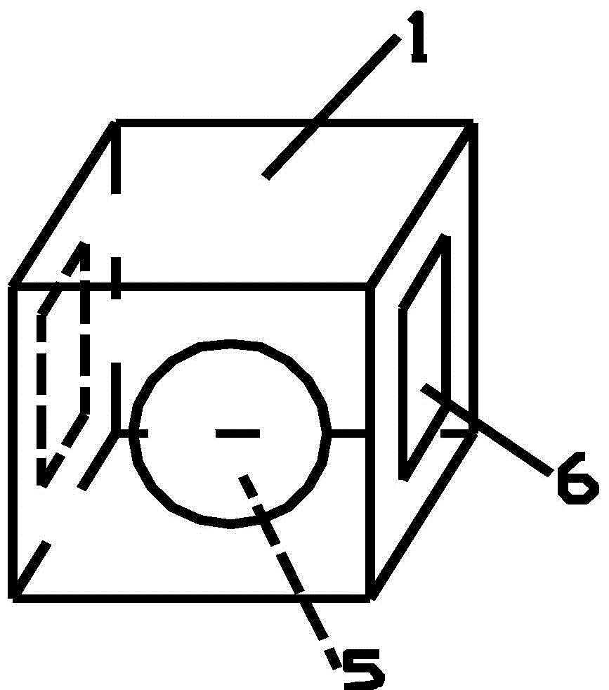
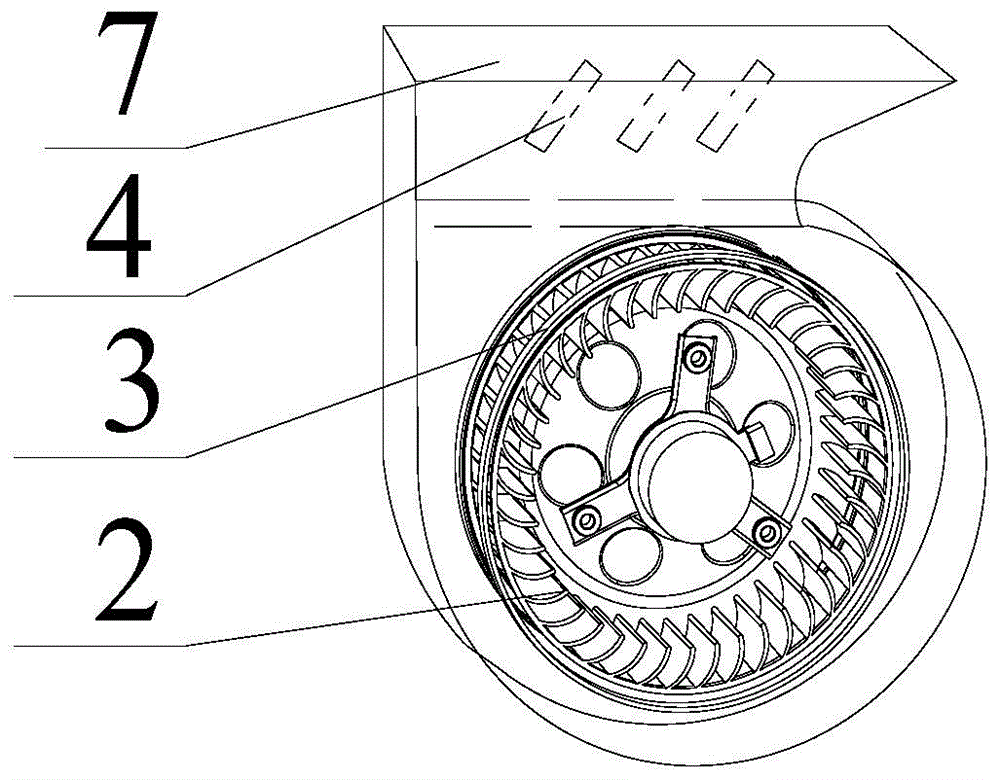
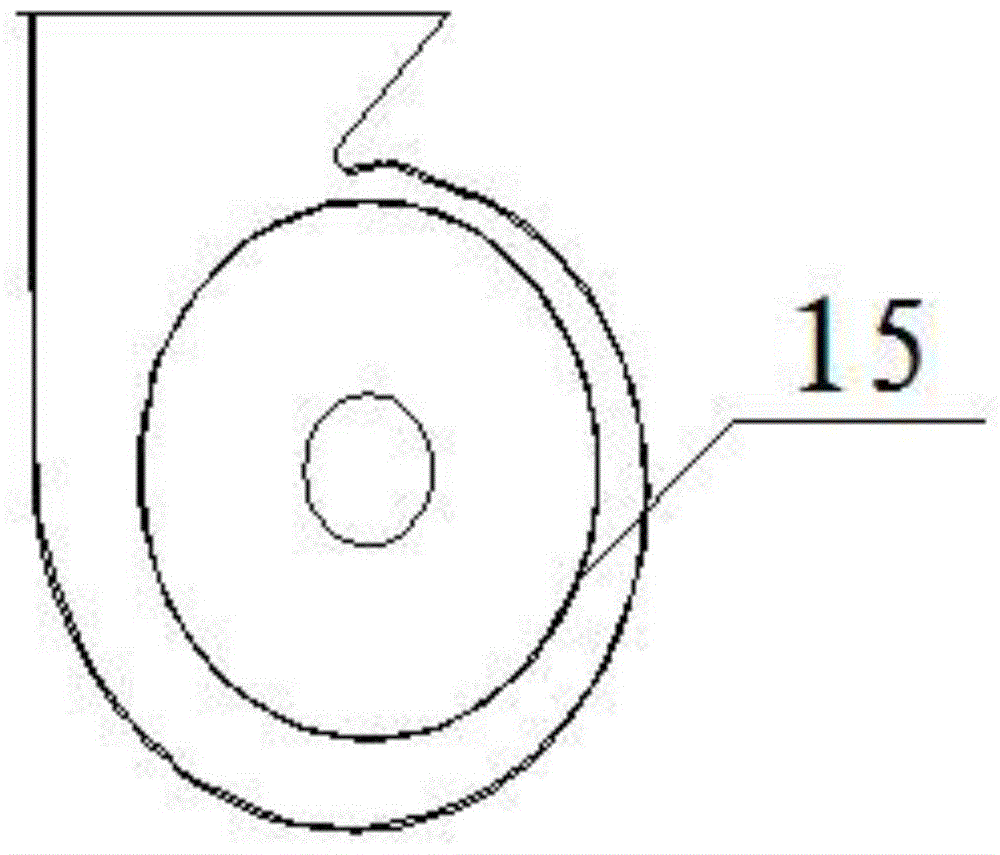
[0023] Specific embodiment 1, such as Figure 1-6 As shown, a wall-mounted air cleaner includes a purifier housing 1 with an air purification device inside, an air inlet 5 is opened on the front panel of the housing, and an air outlet 6 is opened on the two side walls of the housing. , the purification device includes two fans, the air outlets 7 of the two fans communicate with the air outlets 6 on the two side walls of the housing respectively, the air inlets of the two fans communicate with the outlet of the air filter, and the inlet of the air filter It communicates with the air inlet 5 on the front panel of the housing. The fan includes an impeller shell, an impeller arranged in the inner cavity of the impeller shell and fixed on the impeller shaft, and the impeller shaft is connected with the driving device. The key is: the connection between the impeller shell and the impeller The space between constitutes the ventilation duct, and the wind protection ring 15 coaxial wit...


PUM

PropertyMeasurementUnit
diameteraaaaaaaaaa
diameteraaaaaaaaaa
diameteraaaaaaaaaa

Abstract

The invention relates to a wall-hanging air purifier. The wall-hanging air purifier comprises a purifier shell with an air purifying apparatus inside, wherein an air inlet is formed in a front panel of the shell, air outlets are formed in two side walls of the shell, the purifying apparatus comprises two fans, air outlets of the two fans are respectively communicated with the air outlets in the two side walls of the shell, air inlets of the two fans are respectively communicated with an outlet of an air filter, an inlet of the air filter is communicated with the air inlet in the front panel of the shell, each fan comprises an impeller shell and an impeller which is arranged in an inner cavity of the impeller shell and fixed on an impeller shaft, the impeller shaft is connected with a driving apparatus. A key point of the invention is that a gap between the impeller shell and the impeller forms a ventilation air duct, an air protection ring 15 which is coaxial with the impeller is arranged on the impeller shell inner wall, adjacent to a peripheral ring of the impeller, of the ventilation air duct, and the diameter of an air stop annular plate is 6 to 10mm greater than that of the impeller. The wall-hanging air purifier is small in air resistance, smooth in air discharging, high in working efficiency, good in performance, capable of greatly lowering the noise, high in air outlet efficiency and capable of greatly improving the performance.

Description

technical field [0001] The invention relates to an indoor air purifying device, in particular to a wall-mounted air purifier. Background technique [0002] At present, on the wall-mounted air purifier, on the one hand, the air outlet mostly uses two or more ultra-thin small blowers, and the air enters from the middle of the front centrifugal impeller and the air is discharged from the surroundings. The disadvantage is that the air volume is small and the noise is large. The improved wall-mounted air purifier uses a plate-type volute air duct, or several small blowers, with front air inlet and side air outlet. The air duct is designed as two side-by-side air ducts, and the motor drives the centrifugal impeller to rotate. , the airflow is inhaled through the middle of the centrifugal impeller, and under the action of centrifugal force, it flows out from the air outlet along the inner wall of the air duct at a certain speed. However, the disadvantages of this device are large w...

Claims


Application Information

Patent Timeline
Patent Type & Authority Applications(China)
IPC IPC(8): B01D46/00B01D50/00
Inventor 郭天东
Owner 北京卫家环境技术有限公司
Why Eureka
Try Eureka