A core holder for simulating complex migration process of formation fluid and its application method

A core holder, a technology for simulating formations, applied in workpiece clamping devices, applying stable tension/pressure to test material strength, scientific instruments, etc., can solve the problem of strain gauge lead wire and resistance grid strain gauge fracture, rock Complicated core boundary conditions, uneven deformation, etc., to achieve the effect of perfecting the experimental simulation method

Inactive Publication Date: 2016-02-17
SHANDONG UNIV OF SCI & TECH +1
View PDF5 Cites 0 Cited by
  • Summary
  • Abstract
  • Description
  • Claims
  • Application Information

AI Technical Summary

Problems solved by technology

(2) Even if the strain gauge is pasted on the surface of the core, the friction effect between the indenter and the end face of the core during the loading process will also affect the accurate measurement of the strain gauge
In addition, during the loading process, it is easy to cause the strain gauge lead wire and the resistance grid to be squeezed and cause the strain gauge to break.
(3) The square core has high requirements on processing accuracy. Once the verticality of the six end faces of the core deviates, problems such as eccentric compression and uneven deformation will occur.
In fact, this method will cause the side of the core to be under stress constraints with one axially loaded end face, while the other end face will be under displacement constraints, which complicates the boundary conditions of the core.

Method used


Image

  • A core holder for simulating complex migration process of formation fluid and its application method
  • A core holder for simulating complex migration process of formation fluid and its application method

Examples


Embodiment Construction

[0016] The specific embodiment of the present invention will be described in conjunction with the accompanying drawings.

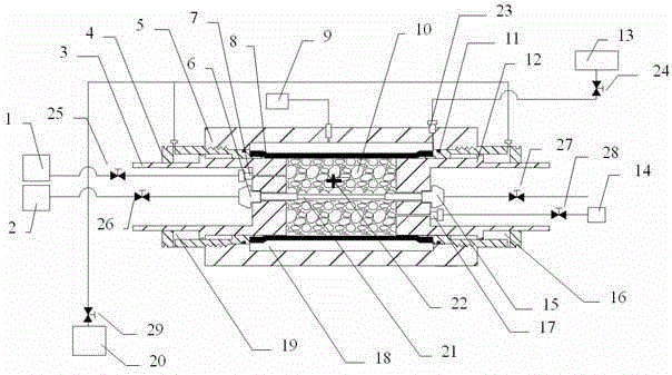
[0017] like figure 1 As shown, the three-axis rock core holder of the present invention is that the left plunger sleeve 4 is connected with the left plunger 3 and the holder cylinder 5, and the right plunger sleeve 11 is connected with the right plunger 12 and the holder cylinder. 5. The left plunger 3 is nested in the left plunger sleeve 4, the right plunger 12 is nested in the right plunger sleeve 11, and there is a left axial pressure cavity 19 between the left plunger sleeve 4 and the left plunger 3 , there is a right end axial pressure cavity 16 between the right end plunger sleeve 11 and the right plunger 12, the rock core 10 is wrapped in the sealing sleeve 10, and its left and right ends respectively contact the left plunger 3 and the right plunger 12, the sealing sleeve 10 and the right plunger 12 respectively. There is an outer ring pressure cha...


PUM


Abstract

The invention discloses a rock core clamp holder capable of simulating complex migration process of formation fluid and a using method of the rock core clamp holder. The clamp holder is a closed combined body formed by an axial compression plunger, a clamp holder barrel body and a pressure-resistant hose embedded in a rock core, wherein the tested rock core is processed to be of a hollow cylindrical shape, the pressure-resistant hose penetrates into a pore passage inside the rock core, the axial compression plunger is arranged at two ends of the rock core, three metering pumps are respectively arranged to be communicated with the axial compression plunger to apply the maximum principal stress to the rock core, are communicated with an inner annular pressure cavity of the clamp holder barrel to apply intermediate principal stress to the rock core, and are communicated with the pressure-resistant hose to apply the minimum principal stress to the inner pore of the rock core; one metering pump is additionally arranged to be communicated with the pore passage deviating from the axis of the plunger to inject the fluid into the rock core; the pressure and the flow rate of pressure transmitting fluid in the liquid chambers are controlled to realize the functions of controlling the stress and the deformation of the rock core. The rock core clamp holder provided by the invention can realize gas / liquid seepage of pores of the rock core under a triaxial stress state and also can meet the rock core deformation and the permeability test during stress relieving.

Description

technical field [0001] The invention relates to the fields of coal mining, coal bed gas and shale gas development, and is used for simulating the migration process of pore fluid in in-situ rock formations under complex working conditions. The invention can not only realize the pore gas / liquid seepage of the rock core under the true triaxial stress state, but also meet the core deformation and permeability test requirements during the stress relief process of the rock core under the stress and displacement boundary conditions, and can also use CT three-dimensional The visualization technology obtains the mesoscopic pore structure of the rock core. Background technique [0002] At present, the stress loading method of most true triaxial rock seepage test devices is realized by respectively applying loads in three directions to six end faces of a cube or cuboid core. This method can better simulate the true triaxial stress state of the rock, but it has a great impact on other ...

Claims


Application Information

Patent Timeline
Patent Type & Authority Patents(China)
IPC IPC(8): G01N15/08G01N3/10B25B11/00
Inventor 王春光蒋宇静王长盛公彬刘继山魏明尧
Owner SHANDONG UNIV OF SCI & TECH
Why Eureka
Try Eureka