
Measuring point switching device used for voltage withstanding test of low-voltage switch appliance

A technology of withstand voltage testing and switching devices, which is applied in the direction of measuring device shells, testing dielectric strength, and improving basic electrical components, etc., which can solve problems such as the influence of measurement accuracy, measurement power fluctuations, and considerable time spent, and achieve saving Effects of conversion time, increased measurement speed, and reduced adverse effects

Inactive Publication Date: 2014-01-29
SHANGHAI UNIV OF ENG SCI
View PDF2 Cites 5 Cited by
  • Summary
  • Abstract
  • Description
  • Claims
  • Application Information

AI Technical Summary

Problems solved by technology

Contacts are used for withstand voltage test. It takes a considerable time for the actuator to drive the electrode contacts to press and leave the corresponding switch electrical measurement point (at least about 1 second for each test point), so that the entire withstand voltage measurement of each switch electrical appliance The time period is used for the clamping of the contact for a long time, which is not conducive to the improvement of the measurement speed
In addition, during the testing process of each switching device, because there are multiple test indicators (phase-to-phase, phase-to-ground, phase-to-shell, etc., taking the RMM1-250 switching device of the People's Electric Appliance Factory as an example, the withstand voltage test has a total of Item 9: Voltage withstand test between the input and output terminals of each phase when the switching device is switched on, A to B phase, A to C phase, B to A phase, B to C phase, C to A phase, and C phase after closing For the withstand voltage test of phase B; the withstand voltage test between each phase of ABC and the housing after closing), if the contact change method is used, it will inevitably cause frequent pressing and separation of the contacts, which is not conducive to each switching device During the test phase, the resistance of the measurement loop formed by the measurement terminal and the test terminal is kept constant, which will easily cause fluctuations in the measurement power supply and affect the accuracy of the measurement.
Moreover, frequent pressing and separation of the contacts can easily lead to poor contact, and arcing is likely to occur when the high-voltage test is applied, which will cause damage to electrical equipment, and oxidation will easily occur on the surface of the contacts, which will adversely affect the correctness of subsequent test results. influences

Method used


Image

  • Measuring point switching device used for voltage withstanding test of low-voltage switch appliance
  • Measuring point switching device used for voltage withstanding test of low-voltage switch appliance

Examples


Embodiment

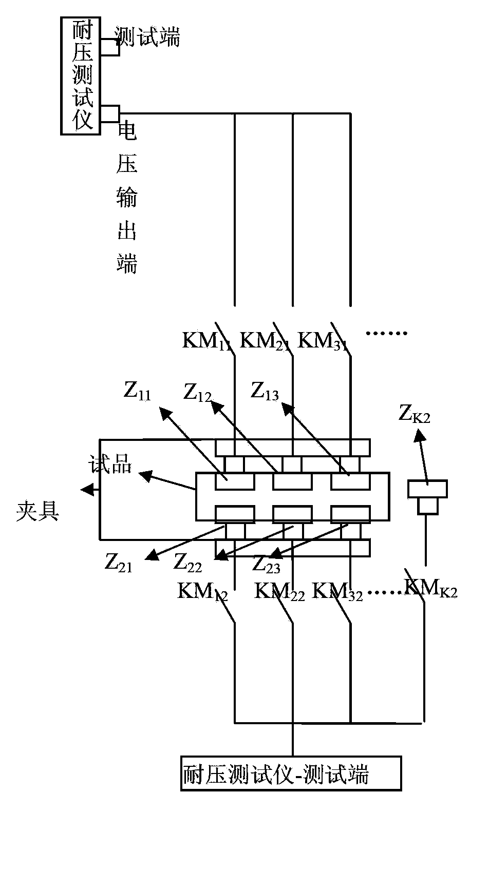
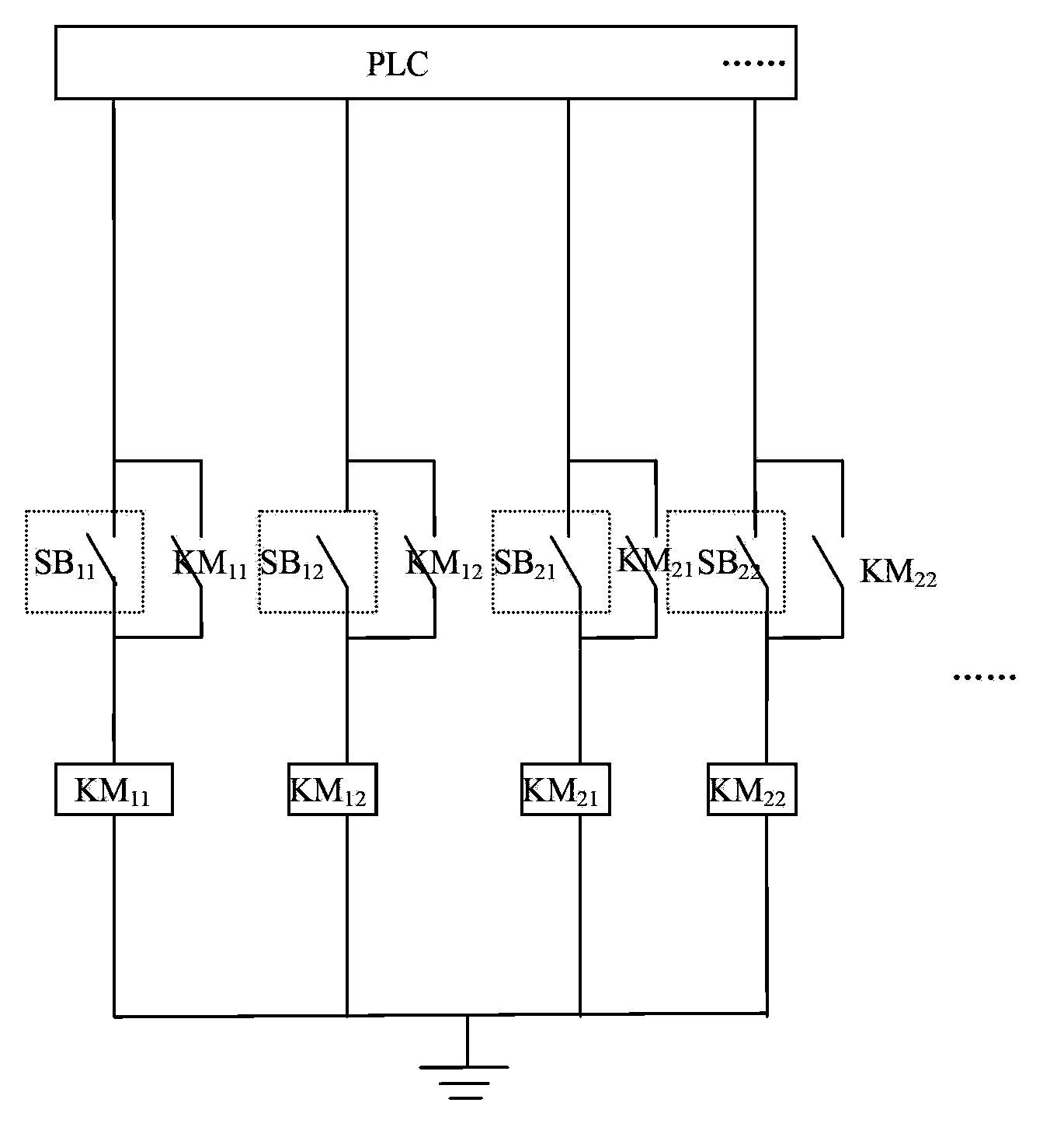
[0016] Such as figure 1 , figure 2 As shown, a measuring point switching device for withstand voltage test of low-voltage switchgear, including withstand voltage tester, connecting contact Z k2 , the first high-voltage relay, the second high-voltage relay, PLC and trigger switch, the voltage output end of the voltage withstand tester and the first contact (KM) of the first high-voltage relay 11 、KM 21 、KM 31 ) input terminal connection, the first contact of the first high voltage relay (KM 11 、KM 21 、KM 31 ) output terminal and the electrode claw (Z 11 ,Z 21 ,Z 31 ) connection, the first contact of the second high voltage relay (KM 12 、KM 22 、KM 32 ) input terminal and the electrode claw (Z 12 ,Z 22 ,Z 32 ) connection, the third contact KM of the second high voltage relay K2 Connecting contact Z with the housing of the switch k2 connected, its output end is connected to the test end of the withstand voltage tester, and the trigger switch (SB 11 , SB 12 , SB ...


PUM


Abstract

The invention relates to a measuring point switching device used for a voltage withstanding test of a low-voltage switch appliance. The measuring point switching device comprises a voltage withstanding tester, a connection contact, a first high-voltage relay, a second high-voltage relay, a PLC (programmable logic controller), a triggering switch and a clamp, electrode claws used for fixing an input end and an output end of a to-be-tested switch appliance are arranged on the clamp, a voltage output end of the voltage withstanding tester is connected with a first contact input end of the first high-voltage relay, a first contact output end of the first high-voltage relay is connected with the electrode claw fixing the input end of the to-be-tested switch appliance, a first contact input end of the second high-voltage relay is connected with the electrode claw fixing the output end of the to-be-tested switch appliance, an output end of the second high-voltage relay is connected with a testing end of the voltage withstanding tester, and one end of the triggering switch is connected with the PLC while the other end of the same is connected with a coil of the first high-voltage relay and a coil of the second high-voltage relay. Compared with the prior art, the measuring point switching device has the advantages of high switching speed, short switching time and the like.

Description

technical field [0001] The invention relates to a technology related to withstand voltage testing of low-voltage switchgear, in particular to a measuring point switching device used for withstand voltage testing of low-voltage switchgear. Background technique [0002] The mechanism currently used for withstand voltage testing of low-voltage switchgear, when testing the withstand voltage performance of multiple test points of switchgear (such as: input to output when the switchgear is opened, each relative phase and relative housing when the switch is closed) During the test, the method of switching between the output terminal of the high voltage test voltage of the withstand voltage tester and the input terminals of each measuring point of the switching device and the output terminal of the measuring point of the switching device and the test terminal of the withstand voltage tester adopts the contact conversion method , that is, first cut off the output voltage source of th...

Claims


Application Information

Patent Timeline
Patent Type & Authority Applications(China)
IPC IPC(8): G01R31/12G01R1/04G01R1/20
Inventor 杜向阳程武山张敏良朱明年顾峰勇毕伟张涓贾聪
Owner SHANGHAI UNIV OF ENG SCI
Learn More