
Method for determining effective excitation points on basis of illumination energy of target strata

A lighting energy and excitation point technology, applied in the direction of seismic signal processing, etc., can solve the problems of not being able to reasonably reflect the underground geological characteristics of complex areas, not being able to accurately determine the position of the encryption shot, and being difficult to obtain geological imaging effects, etc., to improve the lighting intensity, Improve the quality of seismic sections and the effect of uniform energy distribution

Active Publication Date: 2014-01-29
BC P INC CHINA NAT PETROLEUM CORP +1
View PDF3 Cites 19 Cited by
  • Summary
  • Abstract
  • Description
  • Claims
  • Application Information

AI Technical Summary

Problems solved by technology

In this method, after determining the position of the minimum energy bin, according to the coordinates of the bin, select the shot point at the corresponding position on the ground in the spare shot point set for encryption. For complex geological structures, this design cannot accurately determine the position of the encryption shot, and the final The combination of encrypted shots cannot fully improve the illumination of the shadow area of ​​the target layer, and it is difficult to obtain ideal geological imaging effects
[0006] To sum up, there are many conventional methods for optimizing the observation system, but none of them can fully improve the illumination intensity of the shadow area of ​​the target layer. There are few methods for optimizing the observation system based on the illumination energy of the target layer. The energy of the area has been improved to a certain extent, but there are certain deficiencies in practical application, which cannot reasonably reflect the underground geological characteristics of complex areas.

Method used

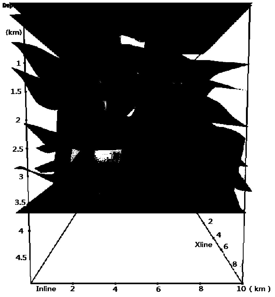
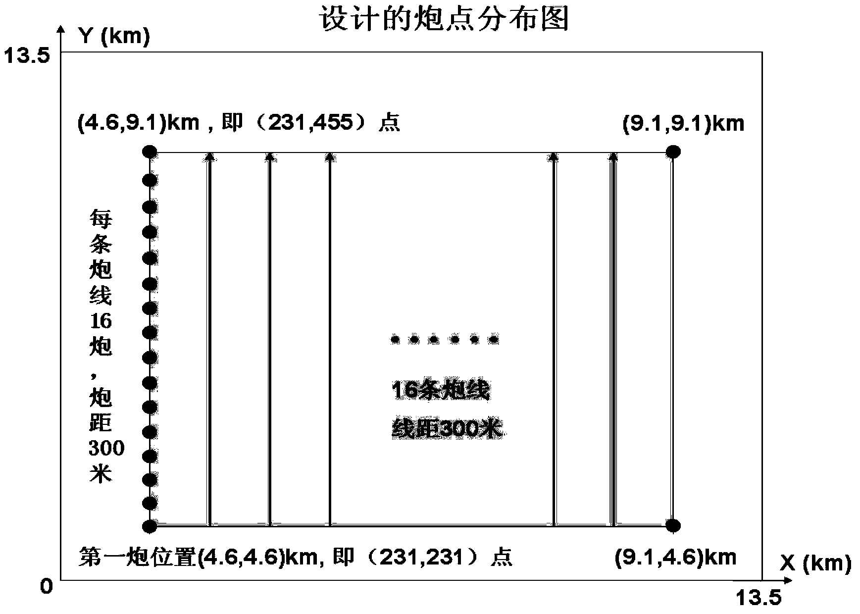
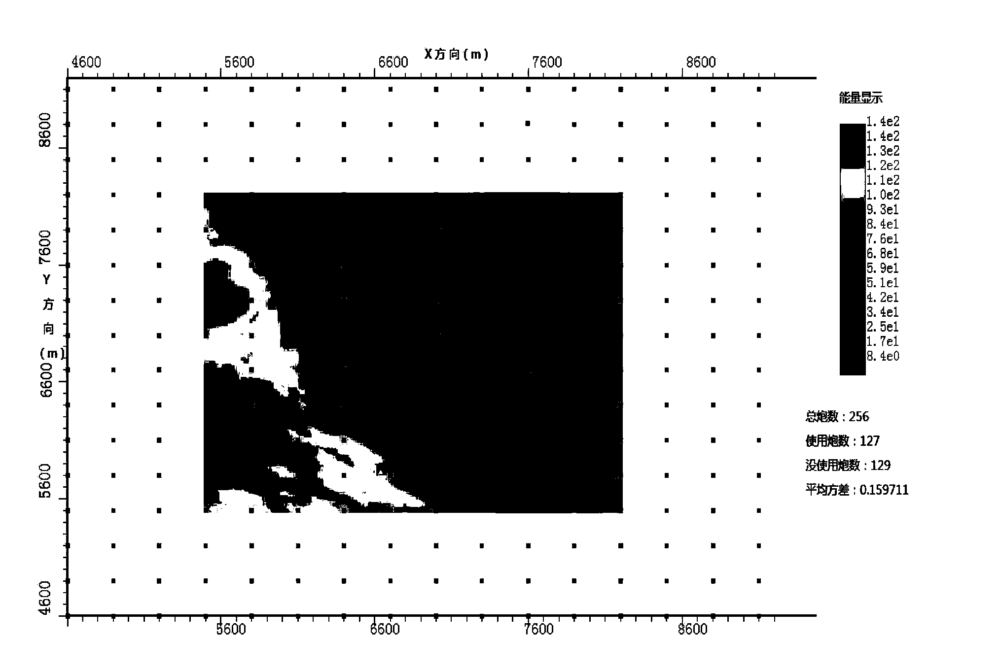

Image

  • Method for determining effective excitation points on basis of illumination energy of target strata
  • Method for determining effective excitation points on basis of illumination energy of target strata
  • Method for determining effective excitation points on basis of illumination energy of target strata

Examples


Embodiment Construction

[0039] The present invention designs the observation system for the target layer on the geological model, performs forward simulation on the observation system after the encrypted shot, obtains the illumination energy of each face element on the target layer for each shot, and determines the minimum energy face element position of the target layer , using the average energy ratio coefficient and the distance energy ratio coefficient to calculate the illumination energy of the minimum energy area of ​​each shot pair in the spare shot point set, and add the shot point selected from the spare shot point set to the shot set composed of the effective excitation point set The average variance of the illumination energy on the target layer determines the effective excitation point, so that the encryption shot point is selected.

[0040] The technology provided by the present invention is mainly to calculate the average energy ratio coefficient and the distance energy ratio coefficient...


PUM


Abstract

The invention discloses a method for determining effective excitation points on the basis of illumination energy of target strata during geophysical prospecting for petroleum. The method includes designing an observation system for the target strata; performing forward modeling on the observation system after shots are infilled in the observation system; acquiring illumination energy generated by each shot for each surface element on the target strata; determining positions of the surface elements with the minimum energy; computing illumination energy of each shot in a standby shot point set for areas with the minimum energy according to average value and distance energy ratios; determining the effective excitation points to select infill shot points according to average variance of the illumination energy of shots in a shot set for the target strata. Shot points selected from the standby shot point set are added into an effective excitation point set to form the shot set. The method has the advantages that the observation system can be effectively arranged in areas with high steep structures, overthrust nappe structures and structures with violent speed horizontal change, the illumination intensity of shadow areas can be improved by the minimum effective excitation points, and the quality of seismic sections can be improved.

Description

technical field [0001] The invention relates to a petroleum geophysical prospecting data processing technology, and is a method for determining an effective excitation point based on the illumination energy of a target layer. Background technique [0002] With the improvement of the degree of exploration, oil and gas exploration in complex areas has become the main target of geophysical exploration workers. Complex areas mainly refer to large surface undulations, complex underground structures, and severe lateral changes in formation velocity. Seismic data information for oil and gas exploration in such areas The noise ratio is generally low, which restricts the accuracy of seismic exploration in this area. Especially in areas where overthrust nappe structures are developed, complex overlying geological structures and the existence of high-speed nappes significantly reduce the illumination intensity of the underlying exploration target layer, making it difficult to image the...

Claims


Application Information

Patent Timeline
IPC IPC(8): G01V1/28
Inventor 许银坡蒋先艺彭文
Owner BC P INC CHINA NAT PETROLEUM CORP
Learn More