Laser light beam collimation device and manufacturing method thereof

A manufacturing method and laser technology, applied in the field of lasers, can solve the problems that the relative position parameters of the laser and the collimating mirror cannot be within the optimal range, the distance cannot be within the predetermined range, and the angle of the collimating mirror cannot be adjusted.

Active Publication Date: 2014-01-29
HISENSE
View PDF5 Cites 5 Cited by
  • Summary
  • Abstract
  • Description
  • Claims
  • Application Information

AI Technical Summary

Problems solved by technology

[0004] In the actual application process, affected by factors such as the processing error of the collimating mirror carrier, the error of the collimating mirror itself, and the assembly error between the collimating mirror and the collimating mirror carrier, even if the processing and assembly design values ​​are in the preset range, still makes the coaxiality of the laser and the collimating mirror and the distance between the optical reference plane of the laser and the corresponding collimating mirror cannot completely match the predetermined range value, so that the collimating mirror cannot fully perform its function and cannot obtain the ideal The spot, which can not meet the requirements of the optical system
Especially in the application of array lasers, due to the error of the consistency of the processing of the collimator carrier and the consistency of the processing of the collimator, the relative position parameters of the laser and the collimator cannot be in the optimal range, so that the collimator not fully functioning
[0005] However, in the prior art, in the actual assembly process, the relative distance between the collimating mirror and the laser cannot be adjusted, and the angle of the collimating mirror cannot be adjusted, so that the coaxiality of the laser and the collimating mirror and the optical The distance between the datum plane and the corresponding collimating mirror cannot be in the predetermined range value

Method used


Image

  • Laser light beam collimation device and manufacturing method thereof
  • Laser light beam collimation device and manufacturing method thereof
  • Laser light beam collimation device and manufacturing method thereof

Examples


Embodiment Construction

[0043] A laser beam collimation device and a manufacturing method thereof according to an embodiment of the present invention will be described in detail below with reference to the accompanying drawings.

[0044] In order to achieve the above object, embodiments of the present invention adopt the following technical solutions:

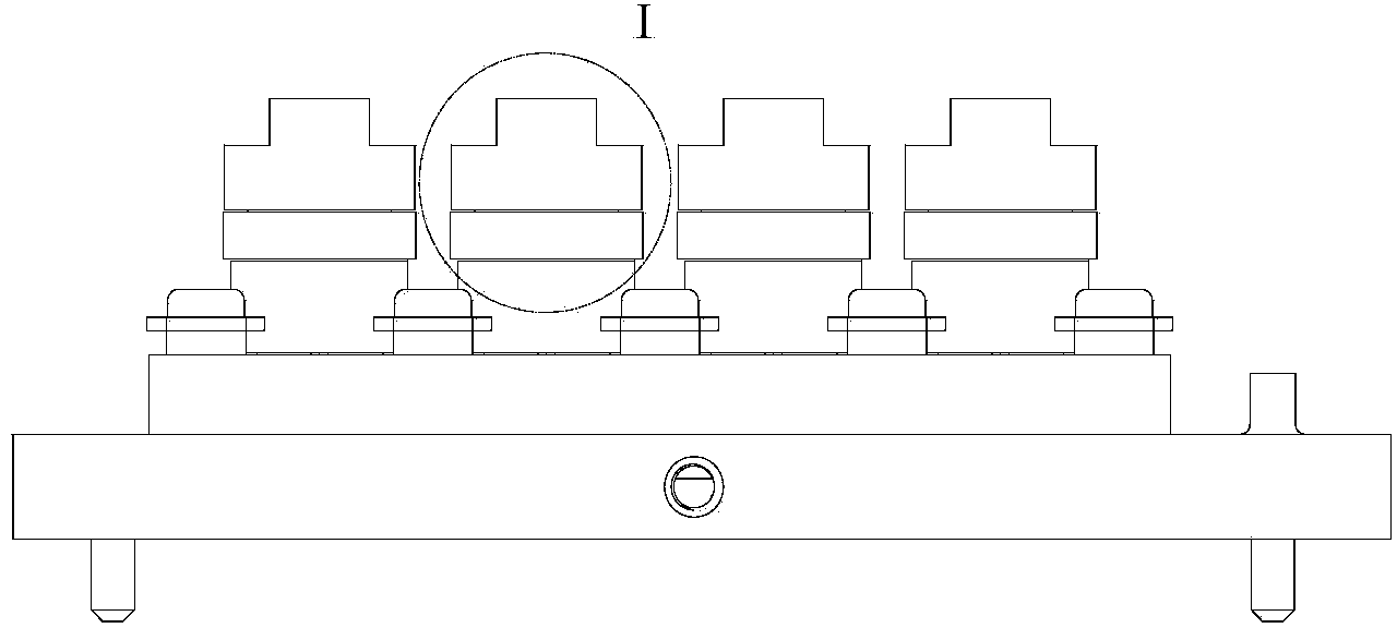
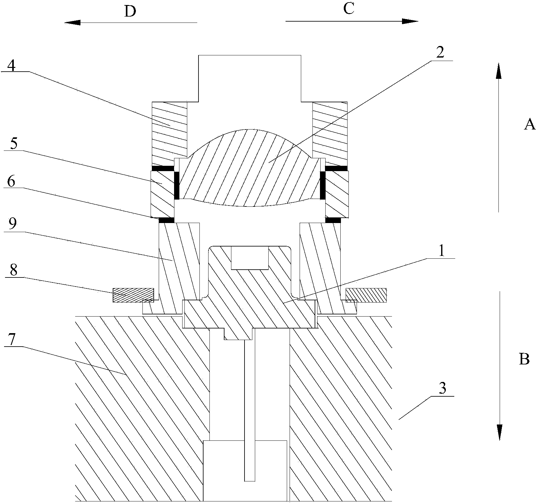
[0045] As shown in Figure 1(a) and Figure 1(b), the laser beam collimation device provided by the embodiment of the present invention includes a laser 1 and a collimating mirror 2 opposite to the laser 1, the laser 1 is fixed on the laser seat 3, and the collimator The straight mirror 2 is fixed on the collimating mirror base 4, and a light-transmitting rigid ring 5 is arranged between the collimating mirror base 4 and the laser base 3, and between the light-transmitting rigid ring 5 and the laser base 3 and / or the collimating mirror base 4 There is a first gap between them, and the first gap is filled with photosensitive adhesive 6 .

[0046] In the...


PUM


Abstract

The invention provides a laser light beam collimation device and a manufacturing method of the laser light beam collimation device, and relates to the technical field of lasers. The laser light beam collimation device is designed to regulate the relative distance and coaxiality between a collimating lens and a laser in the assembling process, and comprises the laser and the collimating lens arranged opposite to the laser, wherein the laser is fixed to a laser base, the collimating lens is fixed to a collimating lens base, a transparent rigid ring is arranged between the collimating lens base and the laser base, a first interval is formed among the transparent rigid ring and the laser base and/or the collimating lens base, and the first interval is filled with photosensitive adhesives. The laser light beam collimation device and the manufacturing method of the laser light beam collimation device can be applied to manufacturing of laser light sources.

Description

technical field [0001] The invention relates to the technical field of lasers, in particular to a laser beam collimation device and a manufacturing method thereof. Background technique [0002] In the current projection equipment market, laser light sources are increasingly showing their strong vitality, and more and more manufacturers have launched various laser projection products one after another. As the core of the laser light source, the laser is an essential and important component. In order to achieve high brightness, the existing laser light source generally arranges dozens of lasers in an array to form an array laser, so as to achieve the required brightness requirement. [0003] Array lasers in the prior art are generally composed of multiple lasers, and each laser in the array laser is configured with a collimating mirror. In practical applications, array lasers have extremely high requirements on the coaxiality between the laser and the collimating mirror, and...

Claims


Application Information

Patent Timeline
Patent Type & Authority Applications(China)
IPC IPC(8): H01S5/02H01S5/06G02B7/02
CPCG02B27/30
Inventor 李强
Owner HISENSE
Why Eureka
Try Eureka