Bearing with an energy production unit, in particular self-aligning roller bearing for the mounting of a roller

A technology for generating units and bearings, applied to roller bearings, rotating bearings, bearings, etc., which can solve the problems of bearing installation costs

Inactive Publication Date: 2014-01-29
SCHAEFFLER TECH AG & CO KG
View PDF10 Cites 16 Cited by
  • Summary
  • Abstract
  • Description
  • Claims
  • Application Information

AI Technical Summary

Problems solved by technology

Furthermore, the retrofitting of bearings already installed in the operat

Method used


Image

  • Bearing with an energy production unit, in particular self-aligning roller bearing for the mounting of a roller
  • Bearing with an energy production unit, in particular self-aligning roller bearing for the mounting of a roller
  • Bearing with an energy production unit, in particular self-aligning roller bearing for the mounting of a roller

Examples


Embodiment Construction

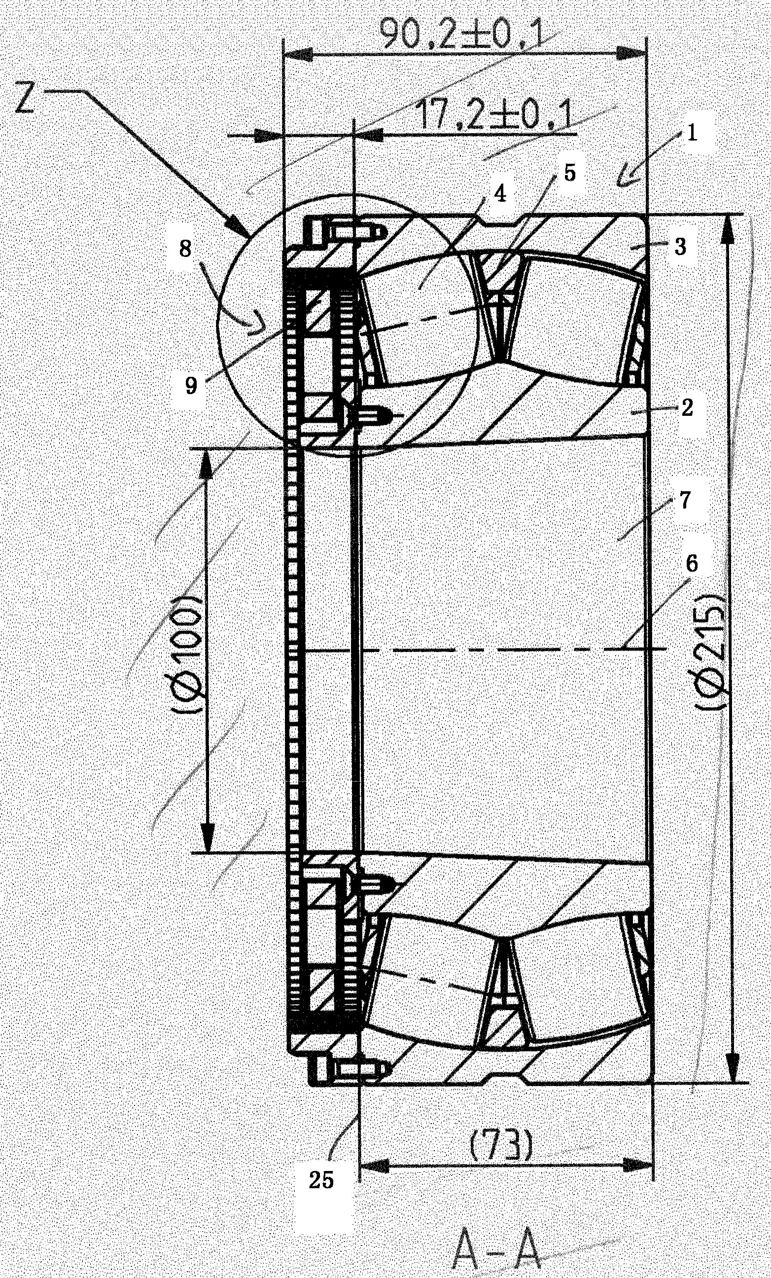
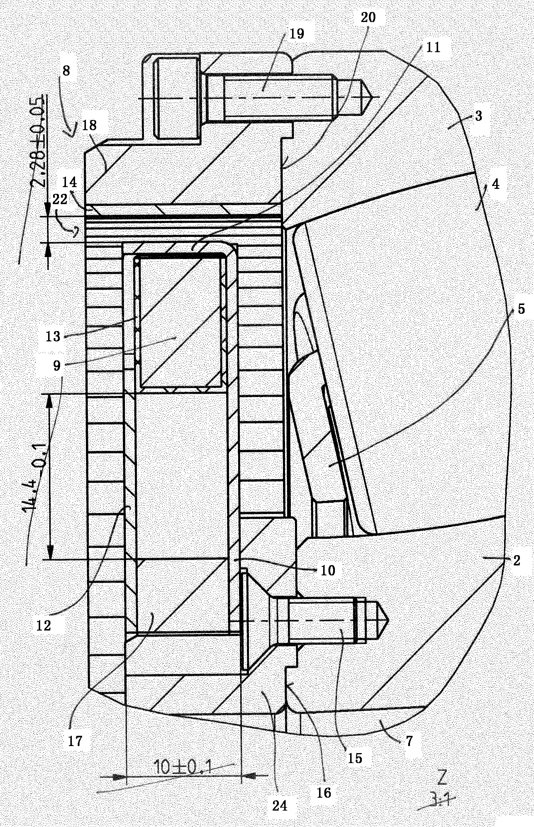
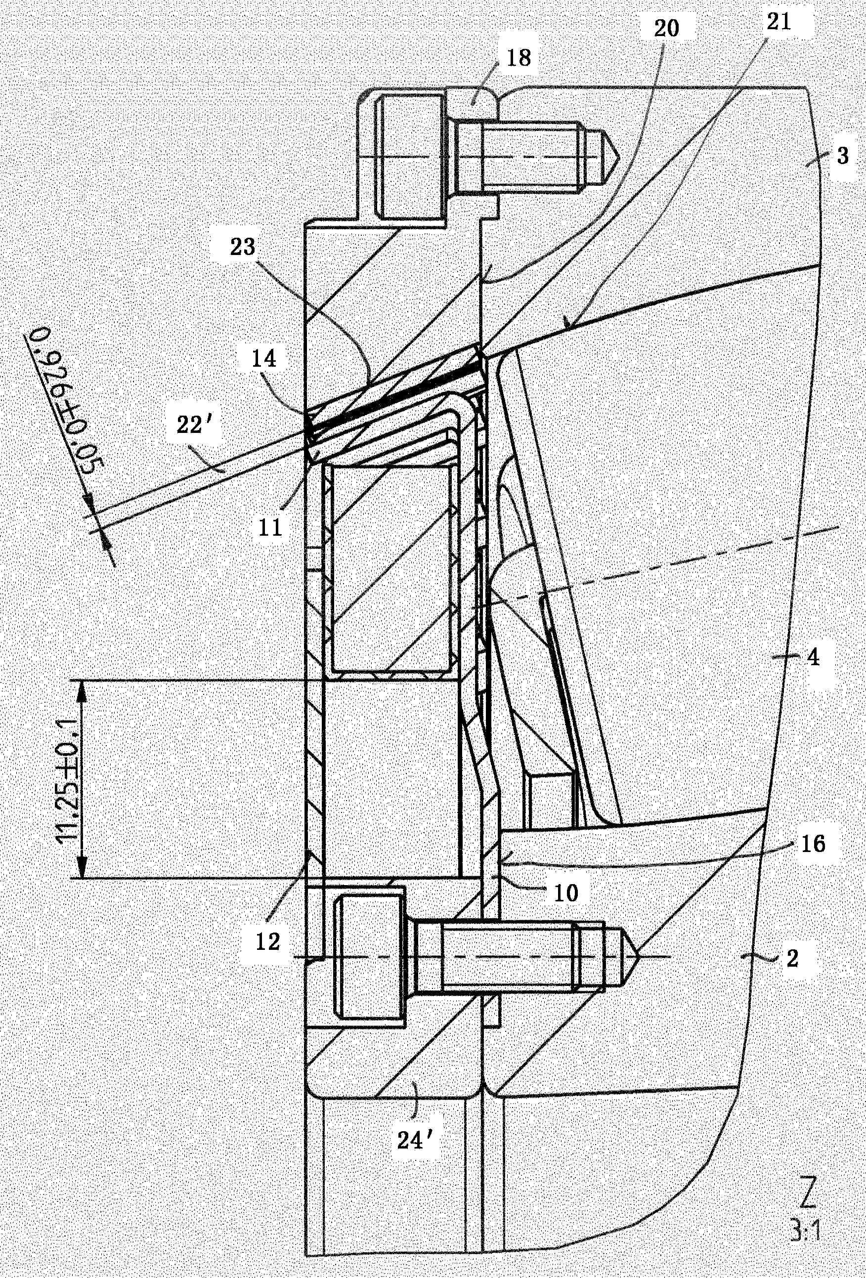
[0027] figure 1 A bearing in the form of a rolling bearing 1 is shown, which comprises a first bearing ring 2 and a second bearing ring 3 . The rolling bearing 1 is designed as a double row and comprises two rows of rolling bodies 4 configured as spherical rollers. The rolling elements 4 are guided by the bearing cage 5 with respect to the axis of rotation 6 of the rolling bearing 1 in the circumferential direction and axially, that is to say essentially parallel to the axis of rotation 6 of the rolling bearing 1 , and are kept spaced apart. The two rows of spherical rollers are arranged staggered upwards from each other.

[0028] Roller bearing 1 is part of a bearing arrangement for rotatably supporting a roll, ie a guide roll for a paper web of a printing press, wherein a conically extending shaft 7 is held rotatable about an axis of rotation 6 .

[0029] The deflection roll has pressure sensors which detect the pressing force of the paper web against the outer peripheral ...


PUM


Abstract

The invention relates to a bearing, in particular rolling contact bearing (1), comprising a first bearing ring (2), a second bearing ring (3) and an energy production unit (8) designed as a claw pole generator, wherein the claw pole generator (8) comprises a first claw ring (10) with a sequence of first claws (11) and a second claw ring (12) which is offset in the revolving direction of the axis of rotation (6) and has a sequence of second claws, wherein the two claw rings (10, 12) surround an induction coil (9) encircling the axis of rotation (6), wherein the claws (11) of the two claw rings (10, 12) together with a sequence of magnetic poles (14) encircling the axis of rotation (6) form magnetic circuits surrounding the induction coil (9). The problem of providing a bearing which permits retrofitting with a claw pole generator is solved according to the invention in that the claw rings (10, 12) and the induction coil (9) are fastened by a first support ring (24; 24') on an end surface (16) of the first bearing ring (2), in that the magnetic poles (14) are fastened on the end surface (20) of the second bearing ring (3) by means of a second support ring (18), wherein the magnetic poles (14) are connected in a magnetically conductive manner to one another by means of a return-path ring made from a magnetically conductive material, and wherein the two claw rings (10, 12) are connected in a magnetically conductive manner by means of a flux-conducting ring (17).

Description

technical field [0001] The invention relates to a bearing according to the preamble of claim 1 and to a bearing arrangement according to claim 11 for the rotatable mounting of a roll, in particular a guide roll for a paper web. Background technique [0002] It is known from practice that, during operation, electrical energy is generated from the rotational movement of bearings, in particular rolling bearings or sliding bearings. For this purpose, in particular rolling bearings are known in which the energy generation unit is structurally integrated. In particular rolling bearings are known in which the energy generating unit is designed as a claw pole generator. The claw pole generator here comprises a first claw ring with a series of first claws extending in the circumferential direction of the rolling bearing, a second claw ring with a series of second claws extending in the circumferential direction of the rolling bearing, separated by two An induction coil surrounded b...

Claims


Application Information

Patent Timeline
IPC IPC(8): F16C23/08F16C43/04H02K1/14H02K7/18F16C41/00
CPCF16C41/004F16C43/04F16C13/02F16C33/7806F16C23/086H02K21/16H02K2213/03H02K1/185H02K7/1846F16C2240/40F16C19/38F16C2226/60H02K7/088H02K7/1807
Inventor 托马斯·林克维尔纳·罗曼海因茨·托伊默马丁·格伦亨利·范德克诺克卡尔·穆勒
Owner SCHAEFFLER TECH AG & CO KG
Why Eureka
Try Eureka