Anti-rotation implant device

An implant and anti-rotation technology, which is applied in the fields of implantology, medical science, dentistry, etc., can solve the problems of large stress concentration of fixing bolts, insufficient anastomosis (not completely passively seated, fixing bolts broken, etc.), and achieve cutting force and Reasonable extrusion force, avoid alveolar bone cracking, and avoid cutting difficulties

Inactive Publication Date: 2014-02-05
DALIAN SANSHENG SCI & TECH DEV
View PDF6 Cites 7 Cited by
  • Summary
  • Abstract
  • Description
  • Claims
  • Application Information

AI Technical Summary

Problems solved by technology

Because the upper end of the implant is not fully anastomosed (not completely passively seated), a large stress concentration may be generated at the fixing bolt, causing the fixing bolt to break; There is a certain internal stress at the bolt after tightening, and it is easy to break under long-term action
[0006] 2. Difficult to be passive
However, due to the internal connection, the hexagonal or octagonal size must be smaller than the inner diameter of the implant, and if the size difference is not large, the inner wall of the implant at the junction will inevitably be very thin, which will cause the material to be weak and easy to break the inner wall; If the size difference is large, the inner diameter of the hexagon or octagon is relatively small, and the corresponding rotational torque will become larger, which is easy to trip and cause structural damage.

Method used


Image

  • Anti-rotation implant device
  • Anti-rotation implant device
  • Anti-rotation implant device

Examples


Embodiment Construction

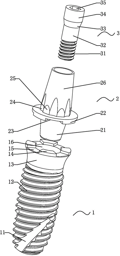
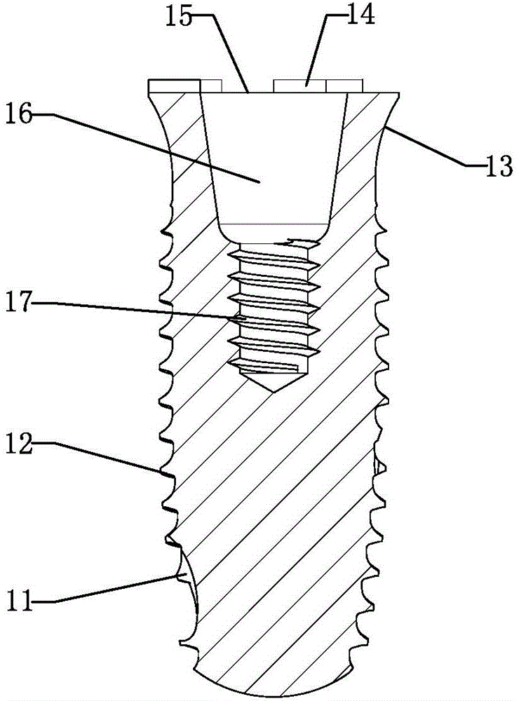
[0033] Such as figure 1 As shown, an anti-rotation implant device includes an implant 1, an abutment 2 and a central bolt 3, all made of pure titanium material, the implant 1 includes a transgingival neck and a head, and the implant The head of 1 is a frustum of a cone, and the large-diameter end of the frustum of the head is close to the gingival neck; the small-diameter end of the frustum of the head is an arc surface 10, and the taper of the frustum of the head is The bionic taper close to the natural tooth root can improve the long-term stability; the outer surface of the head is provided with threads 12, and the outer surface of the head is also provided with three evenly distributed spiral self-tapping grooves 11; The helical direction of the helical self-tapping groove 11 is the same as that of the thread 12 , both are right-handed, and the lead angle of the helical self-tapping groove 11 is greater than that of the thread 12 .

[0034] The spiral self-tapping groove ...


PUM


Abstract

The invention discloses an anti-rotation implant device which comprises an implant, an abutment and a central bolt. The anti-rotation implant device is characterized in that the implant comprises a gum penetrating neck and a head; a thread is arranged on the outer surface of the head; at least two helical self-tapping grooves are formed in the outer surface of the head; connecting holes are formed in the implant and are a positioning hole and a threaded blind hole which are coaxially connected in sequence; at least two positioning embossments are arranged on the upper end surface of the implant body; the abutment comprises a dental crown connecting section and an implant connecting section; an annular positioning table is arranged between the dental crown connecting section and the implant connecting section; positioning grooves matched with the positioning embossments are formed in the annular positioning table; a ladder hole matched with the central bolt is formed in the abutment; the central bolt penetrates through the ladder hole to be connected with the threaded blind hole so as to fix the abutment to the implant. According to the anti-rotation implant device, the positioning embossments on the upper end surface of the implant are matched with the annular positioning table on the abutment, so that a relatively large rotary torque can be born, connection is relatively firm, and the service life is prolonged.

Description

technical field [0001] The invention relates to the technical field of oral medical instruments, in particular to an anti-rotation implant device. Background technique [0002] With the continuous development of oral implant technology, the technology of "artificial dental implant" has gradually matured and stabilized. Artificial dental implants are to first place a highly biocompatible titanium artificial tooth root into the alveolar for fixation and suture, and after a few months, the artificial tooth root is firmly connected to the bone in the alveolar, and then the subsequent denture installation is performed. The artificial tooth root is directly connected to the bone, which can provide better support and is popular because it can chew hard food. [0003] The outside of the implant is a helical structure, which is fixed in the alveolar bone through threads. After being tightly combined with the gum, the abutment is installed, and finally the denture is installed on the...

Claims


Application Information

Patent Timeline
Patent Type & Authority Applications(China)
IPC IPC(8): A61C8/00
Inventor 蔡俊江彭鹏张久文
Owner DALIAN SANSHENG SCI & TECH DEV
Why Eureka
Try Eureka