
An automatic tool changing system for CNC machine tools

A technology of automatic tool change and CNC machine tools, applied in the directions of metal processing mechanical parts, clamping, support, etc., can solve the problems that CNC machine tools cannot replace tools, and the tool status is difficult to monitor, etc., and achieves the effect of simple structure and high processing efficiency.

Inactive Publication Date: 2016-05-18
GUILIN ZHENGLING NO 2 MACHINE
View PDF10 Cites 0 Cited by
  • Summary
  • Abstract
  • Description
  • Claims
  • Application Information

AI Technical Summary

Problems solved by technology

[0003] The technical problem to be solved by the present invention is to provide an automatic tool change system for CNC machine tools, which solves the problem that in the prior art, the state of the tool is difficult to monitor, and the CNC machine tool cannot be replaced in time according to the use status of the tool when no one is on duty. technical problem

Method used


Image

  • An automatic tool changing system for CNC machine tools

Examples


Embodiment Construction

[0018] The principles and features of the present invention are described below in conjunction with the accompanying drawings, and the examples given are only used to explain the present invention, and are not intended to limit the scope of the present invention.

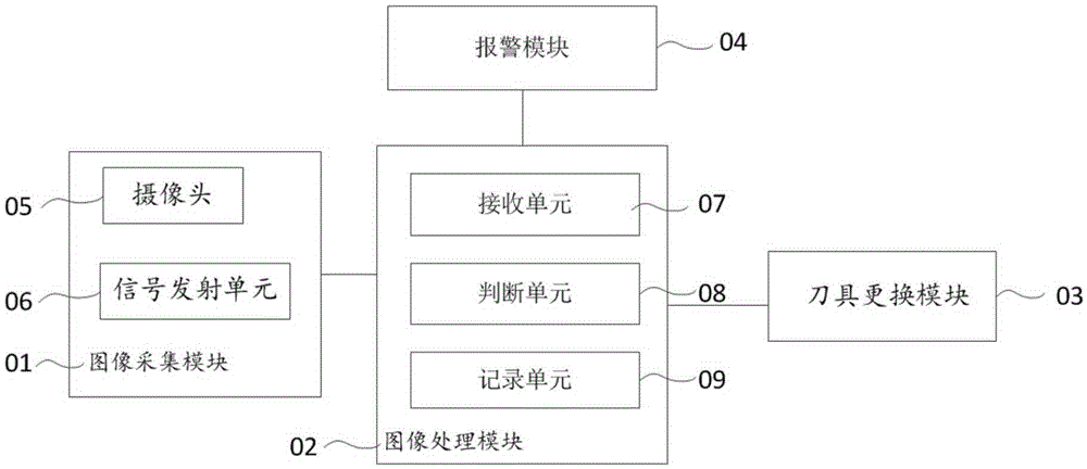
[0019] Such as figure 1 As shown, it is an automatic tool change system for a numerically controlled machine tool according to an embodiment of the present invention, including an image acquisition module 01, an image processing module 02, a tool replacement module 03 and an alarm module 04 connected in sequence,

[0020] The image acquisition module 01 is arranged on the main body of the machine tool, and is used for taking images of tools on the main body of the machine tool, and transmitting the images of the tools to the image processing module 02 . Preferably, the image acquisition module 01 in this embodiment includes a camera 05 and a signal transmitting unit 06, the camera 05 is used to take images of the to...


PUM


Abstract

The invention relates to an automatic cutter changing system for a numerically-controlled machine tool. The system comprises an image acquisition module, an image processing module and a cutter changing module which are sequentially connected, wherein the image acquisition module is used for shooting an image of a cutter on a machine tool main body and transmitting the image of the cutter to the image processing module; the image processing module is used for receiving the image of the cutter and judging whether the size of the cutter on the received cutter image reaches a scrap size; and the cutter changing module is used for receiving a cutter changing instruction and selecting the same cutter to replace the scrapped cutter so as to continue a machining process. The system is simple in structure, realizes monitoring of a running state of the cutter, and can automatically change the cutter according to the monitored cutter state when the numerically-controlled machine tool is in an unattended state; the machining precision of a workpiece is not influenced; the machining time is not waste; the machining efficiency is high; and the system is suitable for extensive application in the machining field.

Description

technical field [0001] The invention relates to the technical field of numerical control machine tools, in particular to an automatic tool changing system for numerical control machine tools. Background technique [0002] In the application process of CNC machine tools, various tools are often involved. During the specific use of the tool, depending on the use environment, use parameters, and use time, the tool will be worn to varying degrees, and the wear of the tool , will directly affect the precision of machining, the efficiency of machining and the economic benefits of enterprises. Especially when the CNC equipment is in a semi-closed state, it is difficult for the operator outside the equipment to observe the state of the tool. If the tool breaks during the processing of the equipment, it may even endanger the personal safety of the operator. Contents of the invention [0003] The technical problem to be solved by the present invention is to provide an automatic too...

Claims


Application Information

Patent Timeline
Patent Type & Authority Patents(China)
IPC IPC(8): B23Q3/155B23Q17/24
CPCB23Q3/155
Inventor 杨晓明何志军蓝春兴沈曙辉罗永新钟桂陆蒋茂军陈国彬
Owner GUILIN ZHENGLING NO 2 MACHINE
Learn More