Track circuit

A track circuit and circuit technology, applied in the direction of electric power track, etc., can solve the problems of signal asymmetry, lack of the function of vehicle equipment to transmit information, lack of insulation damage detection, etc., and achieve the effect of ensuring driving safety

Active Publication Date: 2014-02-05
CRSC RESEARCH & DESIGN INSTITUTE GROUP CO LTD
View PDF5 Cites 23 Cited by
  • Summary
  • Abstract
  • Description
  • Claims
  • Application Information

AI Technical Summary

Problems solved by technology

Among them, the 25Hz phase-sensitive track circuit and the 480-type track circuit can check whether the corresponding section of the rail is in an idle state or an occupied state when the rail is in good contact with the train wheel (the contact resistance is not greater than the standard shunt resistance), that is, under normal circumstances , that is to check whether the corresponding section of the rail is occupied by the train; and when the rail has a bad shunt, the 25HZ phase-sensitive track circuit and the 480-type track circuit will lose the function of checking whether the corresponding section of the rail is idle or occupied; and the 25HZ phase-sensitive track The circuit and the 480-type track circuit also do not have the inspection functions of rail insulation damage, rail breakage and rail lead wire breakage in the corresponding section. The 25HZ phase-sensitive track circuit and the 480-type track circuit cannot keep the rail in an occupied state for maintenance; and they do not have the function of transmitting information to on-board equipment
[0004] The ZPW-2000A integrated track circuit has the function of transmitting information to the on-board equipment; and in the case of good contact between the rail and the train wheel, that is, under normal circumstances, the ZPW-2000A integrated track circuit can check whether the corresponding section of the rail is idle or occupied status, that is, to check whether the rail in the corresponding section is occupied by...

Method used


Image

  • Track circuit
  • Track circuit
  • Track circuit

Examples


Embodiment Construction

[0063] The following will clearly and completely describe the technical solutions in the embodiments of the present invention with reference to the accompanying drawings in the embodiments of the present invention. Obviously, the described embodiments are only some, not all, embodiments of the present invention. Based on the embodiments of the present invention, all other embodiments obtained by persons of ordinary skill in the art without making creative efforts belong to the protection scope of the present invention.

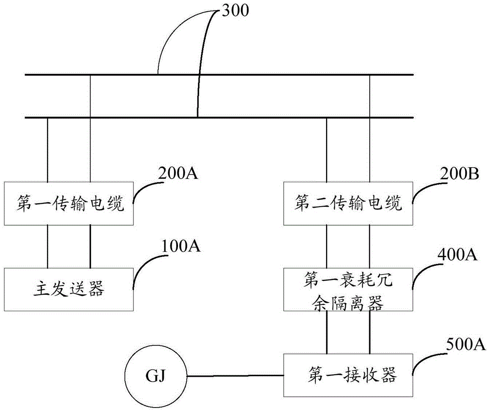
[0064] see figure 1 , showing a schematic structural view of the first embodiment of a track circuit of the present invention, as figure 1 As shown, the track circuit includes: a main transmitter 100A, a first transmission cable 200A, a steel rail 300, a second transmission cable 200B, a first attenuation redundant isolator 400A, a first receiver 500A, and a track relay GJ, wherein:

[0065] The main transmitter 100A is connected to the first end of the rail ...


PUM


Abstract

The invention discloses a track circuit which comprises a main transmitter, a first attenuation redundancy isolator, a first receiver and a track relay, wherein the main transmitter is connected with the first end of a steel track through a first transmission cable, generates mixed frequency-shift pulse signals, and sends the mixed frequency-shift pulse signals out through the steel track; the first attenuation redundancy isolator is connected with the second end of the steel track through a second transmission cable and divides the received mixed frequency-shift pulse signals into frequency-shift signals and pulse signals; the first receiver is connected with the first attenuation redundancy isolator; the track relay is connected with the first receiver; the first receiver is used for receiving the frequency-shift signals and the pulse signals, and performing analytical treatment on the frequency-shift signals and the pulse signals, comparing treated results with the preset condition, and driving the track relay to work according to the compared result. According to the track circuit provided by the invention, the frequency-shift signals and pulse signals are integrated into a whole, and various conditions which possibly occur on the steel track are considered comprehensively, so that safe driving of trains can be ensured.

Description

technical field [0001] The invention relates to the field of rail transit automation, and more specifically relates to a rail circuit. Background technique [0002] With the rapid development of railway construction, track circuits have been widely used in my country as the basic safety equipment of railway signals. Track circuits are circuits composed of rails of a section of railway line as conductors, which are used to automatically and continuously detect whether a certain section of line is used by rolling stock. Occupied to ensure the safety of driving. [0003] At present, the railway circuits used in the station usually include 25Hz phase-sensitive track circuits, 480-type track circuits, high-voltage pulse track circuits and ZPW-2000A integrated track circuits. Among them, the 25Hz phase-sensitive track circuit and the 480-type track circuit can check whether the corresponding section of the rail is in an idle state or an occupied state when the rail is in good cont...

Claims


Application Information

Patent Timeline
IPC IPC(8): B60M1/30
Inventor 任国桥徐宗奇任军赵自信李建清李智宇王智新赵鹏翀张琦史宏飞刘琰琼
Owner CRSC RESEARCH & DESIGN INSTITUTE GROUP CO LTD
Why Eureka
Try Eureka