
A Combined Ducted Aerial Reconnaissance Robot

A combined and robotic technology, applied to rotorcraft, aircraft, motor vehicles, etc., can solve problems such as limited lift and fast maneuvering, and achieve the effects of increasing lift, improving efficiency, and reducing storage troubles

Active Publication Date: 2015-10-28
北京华信智航科技有限公司
View PDF6 Cites 0 Cited by
  • Summary
  • Abstract
  • Description
  • Claims
  • Application Information

AI Technical Summary

Problems solved by technology

Due to its symmetrical design, the four-rotor robot makes the original bulky ducted robot flexible and free, but the traditional four-rotor is flexible, but the lift provided is very limited
This shortcoming is especially prominent in windy conditions, and rapid maneuvering is significantly restricted

Method used


Image

  • A Combined Ducted Aerial Reconnaissance Robot
  • A Combined Ducted Aerial Reconnaissance Robot
  • A Combined Ducted Aerial Reconnaissance Robot

Examples


Embodiment Construction

[0037] The present invention will be further described in detail with reference to the accompanying drawings and embodiments.

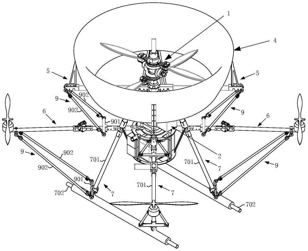
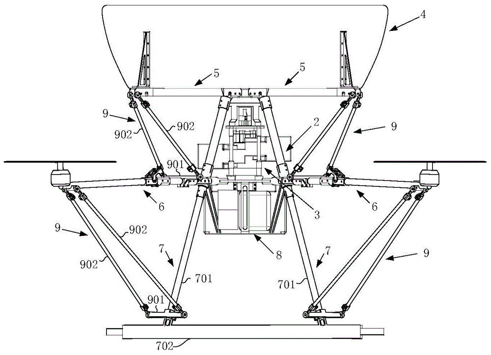
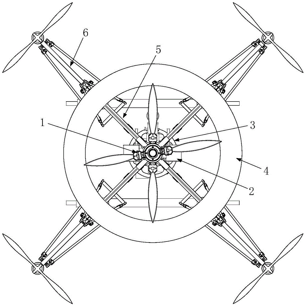
[0038] Aerial reconnaissance robot of the present invention comprises coaxial anti-propeller mechanism 1, gasoline engine 2, engine frame 3, duct 4, duct support mechanism 5, rotor support mechanism 6, main support mechanism 7, as figure 1 , figure 2 , image 3 shown;

[0039] The coaxial anti-propeller mechanism 1 includes a shaft assembly 101, a blade flange 102 and a blade 103, such as Figure 4 As shown; wherein, the shaft assembly 101 is a cross-shaped structure composed of a horizontal shaft 101a and a vertical shaft 101b. The left and right ends of the horizontal axis 101a and the upper and lower ends of the vertical axis 101b are bearing-fitted with bevel gears 104, a total of four bevel gears 104; adjacent bevel gears 104 mesh with each other to form a differential gear mechanism. The upper and lower ends of the longitudinal axis 101b ar...


PUM


Abstract

The invention discloses a combined type ducted aerial reconnaissance robot which comprises a coaxial reverse paddle mechanism, a gasoline engine, an engine frame, a duct, a duct support mechanism, four sets of rotary wing paddle support mechanisms and a main support mechanism, wherein the coaxial reverse paddle mechanism is provided with an upper paddle and a lower paddle which are driven by the gasoline engine, so that the differential motion between the upper paddle and the lower paddle can be realized; the coaxial reverse paddle mechanism is arranged in the duct supported by the duct support mechanism; four horizontal rotary wings which are driven by a motor are evenly arranged along the circumferential direction of the robot by rotary wing support rods; the duct support mechanism and the rotary wing paddle support mechanisms are supported by the main support mechanism, and the whole robot is supported by the duct support mechanism and the rotary wing paddle support mechanisms. The combined type ducted aerial reconnaissance robot has the advantages that the characteristics of a ducted robot and the characteristics of a four-rotary-wing robot are combined together; an oil-electricity hybrid flight mode is adopted, the characteristic of large lift force of the duct is utilized, and the flexibility of the four rotary wings is combined, so that the combined type ducted aerial reconnaissance robot makes up the unstable flight characteristics of the duct.

Description

technical field [0001] The invention belongs to the field of mechanical design and robot technology, and specifically relates to a combined ducted aerial reconnaissance robot. Background technique [0002] Unmanned Aerial Vehicles (UAVs) capable of autonomous flight are widely used in many ways, and are currently mainly used in the military. There are many advantages to using drones to perform missions. For example, the financial and political impact of losing a drone during a mission will be much reduced, so drones can be sent to perform some more dangerous tasks. Although fixed-wing drones have many advantages and are technically mature, they have an obvious disadvantage, that is, they need some catapult devices or runways to "run up" when they take off, and some catapults when landing. A netted device or parachute. For some environments with limited space and loads, the application of this type of drone is greatly restricted. Vertical takeoff and landing technology (VT...

Claims


Application Information

Patent Timeline
Patent Type & Authority Patents(China)
IPC IPC(8): B64C27/02
Inventor 梁建宏吴海亮韩晨皓张以成沈奇杨兴帮吴耀高涵
Owner 北京华信智航科技有限公司
Learn More