
Connecting rod structure for piston

A technology of piston connecting rod and connecting rod, applied in the direction of piston, cylindrical piston, plunger, etc., can solve the problems of friction pair corrosion, high crankcase pressure, oil dilution, etc., and achieve the effect of sealing

Inactive Publication Date: 2014-02-05
ANHUI ZHONGDING POWER
View PDF5 Cites 1 Cited by
  • Summary
  • Abstract
  • Description
  • Claims
  • Application Information

AI Technical Summary

Problems solved by technology

[0003] The purpose of the present invention is to provide a piston connecting rod structure to solve the problem that the traditional piston and connecting rod structure cause gas and exhaust gas to pump exhaust gas into the crankcase during the scavenging process, resulting in high crankcase pressure, oil dilution and friction The problem of vice being corroded

Method used


Image

  • Connecting rod structure for piston
  • Connecting rod structure for piston
  • Connecting rod structure for piston

Examples


Embodiment approach

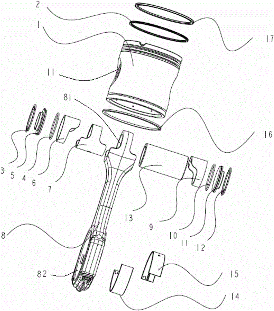
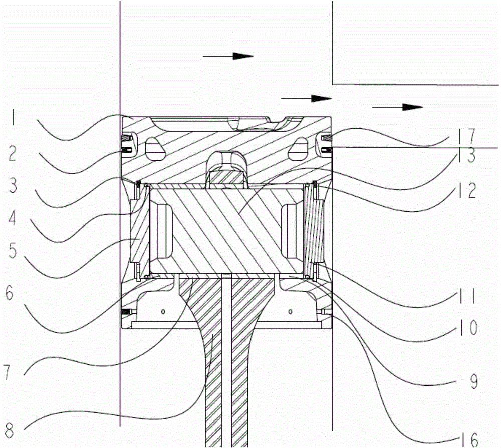
[0022] In further embodiments of the present invention, please continue to refer to figure 1 shown. A gas ring groove is opened around the upper end of the piston 1, and a gas ring 17 is installed in the gas ring groove. A gas ring groove is opened around the lower two ends of the piston 1, and a gas ring 16 is installed in the gas ring groove.

[0023] In a further embodiment of the present invention, an oil ring groove is opened around the upper end of the piston 1 , and an oil ring 2 is installed in the oil ring groove.

[0024] In a further embodiment of the present invention, the opening position of the oil ring groove is lower than the opening position of the gas ring groove at the upper end of the piston 1 .

[0025] In a further embodiment of the present invention, a retaining ring 3 is sleeved on the outside of the piston pin cover 5 , and a spring retaining ring 12 is sleeved on the outside of the piston pin cover 11 . Annular grooves are provided in the two conne...


PUM


Abstract

The invention discloses a connecting rod structure for a piston. The connecting rod structure comprises a connecting rod, the piston, a connecting rod bearing pad and two piston bearing pads, and further comprises two piston pin covers, wherein a through hole is formed in each of the upper end and the lower end of the connecting rod; two connecting holes are formed in circumferential end surface of the piston in a penetrating manner, the upper end of the connecting rod is sleeved with the piston, the two connecting holes are communicated with the through holes formed in the upper end of the connecting rod; the connecting rod bearing pad is arranged inside the through holes formed in the upper end of the connecting rod and the connecting holes, a piston pin is arranged inside the connecting rod bearing pad, and the middle part of the piston pin is sleeved with the connecting rod bearing pad; the two piston bearing pads are arranged inside the two connecting holes respectively, and the two ends of the piston pin are sleeved with the two piston bearing pads; each of the two piston pin covers is sleeved with an O-shaped sealing ring. By adopting the connecting rod structure for the piston, the problem of exhaust gas backflow during the process of scavenging air by an engine can be solved through O-shaped sealing rings in the piston pin covers and two gas rings arranged at two ends of each piston pin hole.

Description

technical field [0001] The invention relates to the technical field of a two-stroke engine with opposed pistons and opposed cylinders, in particular to a piston connecting rod structure. Background technique [0002] In the connecting rod, piston and piston pin assembly of the opposed piston and opposed cylinder engine, when the piston and piston pin reciprocate in the cylinder, due to the structure of the opposed two-stroke engine and the particularity of the intake and exhaust, the traditional piston 1. The connecting rod structure makes the gas and exhaust gas continuously pump exhaust gas into the crankcase during the scavenging process, resulting in too high crankcase pressure. First: The exhaust gas entering the crankcase will dilute the oil in the oil pan, accelerating the deterioration and aging of the oil. After the acid gas enters the engine oil, it will corrode the parts and accelerate the wear along with the lubrication system to each moving pair. Second: The e...

Claims


Application Information

Patent Timeline
Patent Type & Authority Applications(China)
IPC IPC(8): F02F11/00F02F3/00F16J1/16
Inventor 宋莉莉黄永刚李传友左朝凤郭国祥
Owner ANHUI ZHONGDING POWER
Learn More