
Reinforced type protective cover for pressure regulating valve

A technology of protective cover and pressure regulating valve, which is applied in valve details, valve device, valve shell structure, etc., can solve the failure of pressure regulating function of pressure regulating valve, affecting the pressure regulating accuracy of pressure regulating valve, and corrosion of parts and upper valve cover. And other issues

Inactive Publication Date: 2014-02-05
罗达健
View PDF6 Cites 3 Cited by
  • Summary
  • Abstract
  • Description
  • Claims
  • Application Information

AI Technical Summary

Problems solved by technology

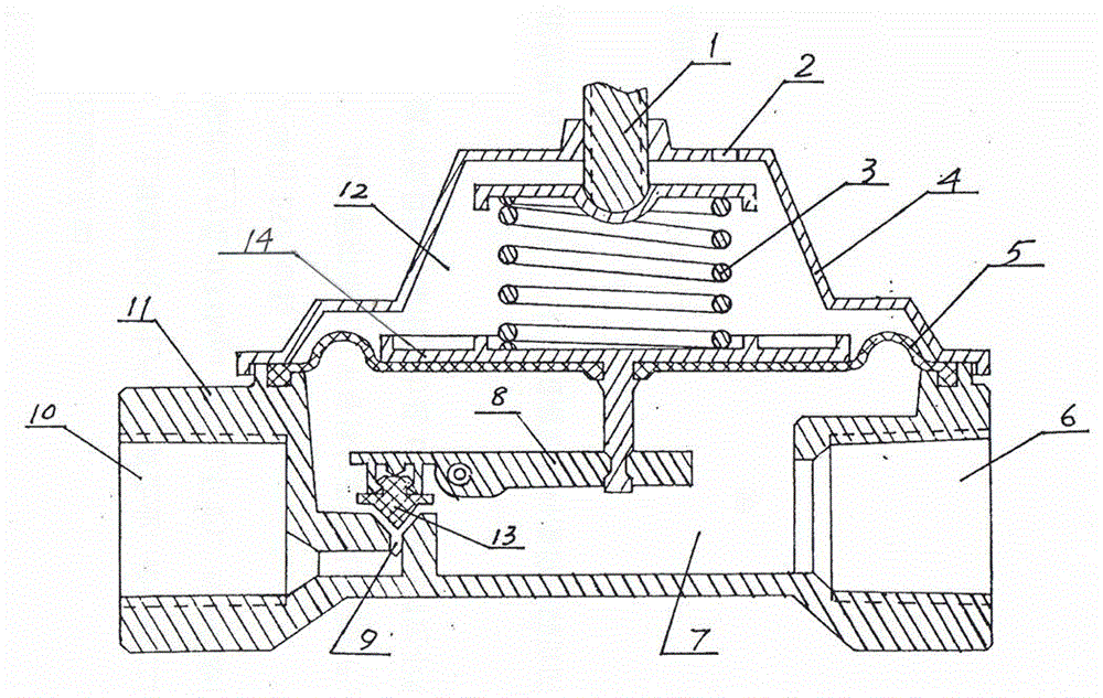
[0004] It can be seen that the breathing hole 2 of the upper valve cover 4 is in a smooth state, which is crucial to the pressure regulating and stabilizing effect of the pressure regulating valve. , when the breathing hole 2 is blocked by dust, sundries, rainwater mixture or snow covers the breathing hole 2 in winter, the air in the upper chamber 12 cannot enter and exit normally, and the pressure regulating function of the pressure regulating valve will fail. accident happened
If rainwater or dust directly enters the upper chamber 12 through the breathing hole 2, it will gather on the diaphragm 5 and the tray 14, causing the diaphragm 5 to bear extra gravity, seriously affecting the pressure stabilization accuracy of the pressure regulating valve, and accident happened
If rainwater (including acid rain) and dust enter the upper chamber 12, it will corrode the parts of the upper chamber 12 and the upper valve cover 4, causing the pressure regulator to lose its pressure regulating function until it is damaged

Method used


Image

  • Reinforced type protective cover for pressure regulating valve
  • Reinforced type protective cover for pressure regulating valve
  • Reinforced type protective cover for pressure regulating valve

Examples


Embodiment Construction

[0014] The present invention is described in further detail by the following examples.

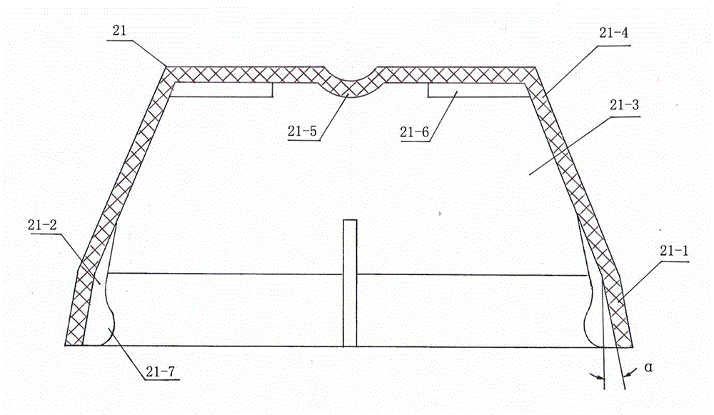
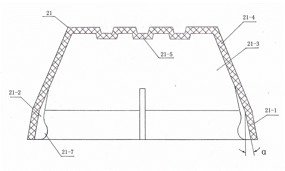
[0015] see figure 2 , image 3 As shown, a protective cover 21 for a pressure regulating valve is composed of a cover body 21-4 and a skirt 21-1. The skirt 21-1 matches and engages with the outer contour of the joint portion between the upper valve cover and the valve seat of the pressure regulating valve. At least one vertical rib or groove 21-2 is provided on the inner wall of the skirt 21-1, and the cavity 21-3 of the cover body 21-4 accommodates the upper valve cover and leaves a gap. At least one inner boss 21-5 and / or at least one reinforcing rib 21-6 are provided on the top inner wall of the cover body 21-4 near the corresponding upper valve cover breathing hole, and these inner bosses 21-5 or reinforced The ribs 21-6 can be arranged on the top inner wall of the whole cover body 21-4, but can not be positioned at the breathing hole of the upper valve cover, so as not to block th...


PUM


Abstract

The invention provides a reinforced type protective cover for a pressure regulating valve. The reinforced type protective cover comprises a cover body and a skirt edge, wherein the skirt edge is matched and connected with the upper valve deck of the pressure regulating valve and the outer outline of a valve seat bonding part; at least one vertical convex rib or groove is formed in the inner wall of the skirt edge; an upper valve deck and a gap are arranged in the cavity of the cover body; at least one inward lug boss and / or at least one reinforced rib are / is arranged on the inner wall of the upper top part of the cover body and near corresponding upper valve deck blowhole(s); at least one convex button is arranged at the lower part of the inner wall of the skirt edge. With adoption of the reinforced type protective cover disclosed by the invention, the situation that the blowholes in the upper valve deck of the pressure regulating valve are communicated with the atmosphere in any bad weather and environment is ensured, so that the service life of the pressure regulating valve is prolonged and the working reliability of the pressure regulating valve is improved.

Description

technical field [0001] The invention relates to the technical field of pressure regulating valve protection, in particular to a reinforced protective cover for a pressure regulating valve. Background technique [0002] The pressure regulating valve widely used in fluid pipelines is mainly composed of an adjusting wheel shaft 1, an adjusting spring 3, a diaphragm 5, a valve core 13, a lever 8, a nozzle 9, an inlet fluid pipe 10, an outlet fluid pipe 6, an upper valve cover 4 and a valve seat 11, see figure 1 shown. A diaphragm 5 is installed between the upper bonnet 4 and the valve seat 11, and the pressure regulating valve is divided into upper and lower chambers 12 and 7. The short arm end of the lever 8 is provided with a valve core 13, and the long arm end is provided with Tray 14, the tray 14 is placed on the surface of the membrane 5 and fixed with the center of the membrane 5. The upper chamber 12 is provided with an adjustment wheel shaft 1 and an adjustment spring...

Claims


Application Information

Patent Timeline
Patent Type & Authority Applications(China)
IPC IPC(8): F16K27/08
CPCF16K27/08
Inventor 罗达健
Owner 罗达健
Learn More