System capable of automatically controlling height of flowerpot

A flowerpot and height technology, applied in the direction of use feedback control, container cultivation, botany equipment and methods, etc., can solve the problem that the flowerpot cannot receive sunlight, etc., and achieve normal ventilation, energy saving, and strong expansion and contraction ability Effect

Active Publication Date: 2014-02-05
SUZHOU JINCHUANG INTERNET TECH CO LTD
View PDF5 Cites 5 Cited by
  • Summary
  • Abstract
  • Description
  • Claims
  • Application Information

AI Technical Summary

Problems solved by technology

[0004] The purpose of the present invention is to provide a system that can automatically control the height of the flower pots, so as to overcome the problem in the prior art that the flower pots under the window sill cannot receive sunlight

Method used


Image

  • System capable of automatically controlling height of flowerpot
  • System capable of automatically controlling height of flowerpot
  • System capable of automatically controlling height of flowerpot

Examples


Embodiment 1

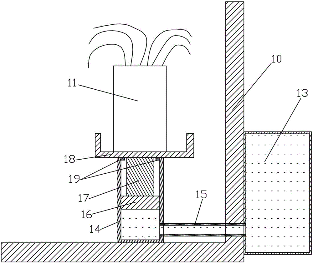
[0023] Such as figure 1 As shown, a system that can automatically control the height of flower pots includes a flower pot 11 placed on the inside of the window sill wall 10, a liquid storage bucket 14 installed under the flower pot 11, and a heat-absorbing bucket 13 installed on the outside of the window sill wall 10 . The heat-absorbing bucket 13 communicates with the liquid bucket 14 through a pipe 15 , and the pipe 15 is set through the window sill wall 10 . Liquid is housed in the heat-absorbing barrel 13 and the liquid holding barrel 14 . The heat-absorbing barrel 13 can absorb the heat of sunlight and make the liquid in the heat-absorbing barrel 13 absorb heat. The liquid holding barrel 14 is equipped with a main piston 16 that can move up and down. The main piston 16 is connected with a piston rod 17 , and the piston rod 17 is connected with the bottom of the flower pot 11 through a support plate 18 .

[0024] Such as figure 1 As shown, the top of the inner surface ...

Embodiment 2

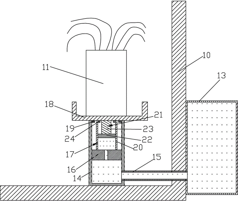
[0029] Such as figure 2 As shown, the only difference between the second embodiment and the first embodiment is that the second embodiment improves the piston rod 17 on the basis of the first embodiment. The piston rod 17 includes a main rod body 20 and a set of pushing devices 21 . The pushing device 21 includes a secondary moving piston 22 and a secondary moving rod body 23, the secondary moving piston 22 is connected with the secondary moving rod body 23, and the secondary moving piston 22 is installed in the main rod body 20 to move up and down, and the secondary moving rod body 23 and the secondary moving rod body 23 The flower pot 11 is connected, and the space formed by the secondary moving piston 22 , the main rod body 20 and the main piston 16 communicates with the liquid storage barrel 14 . The space formed by the secondary moving piston 22 , the main rod body 20 and the main piston 16 communicates with the liquid storage barrel 14 through a channel opened on the m...

Embodiment 3

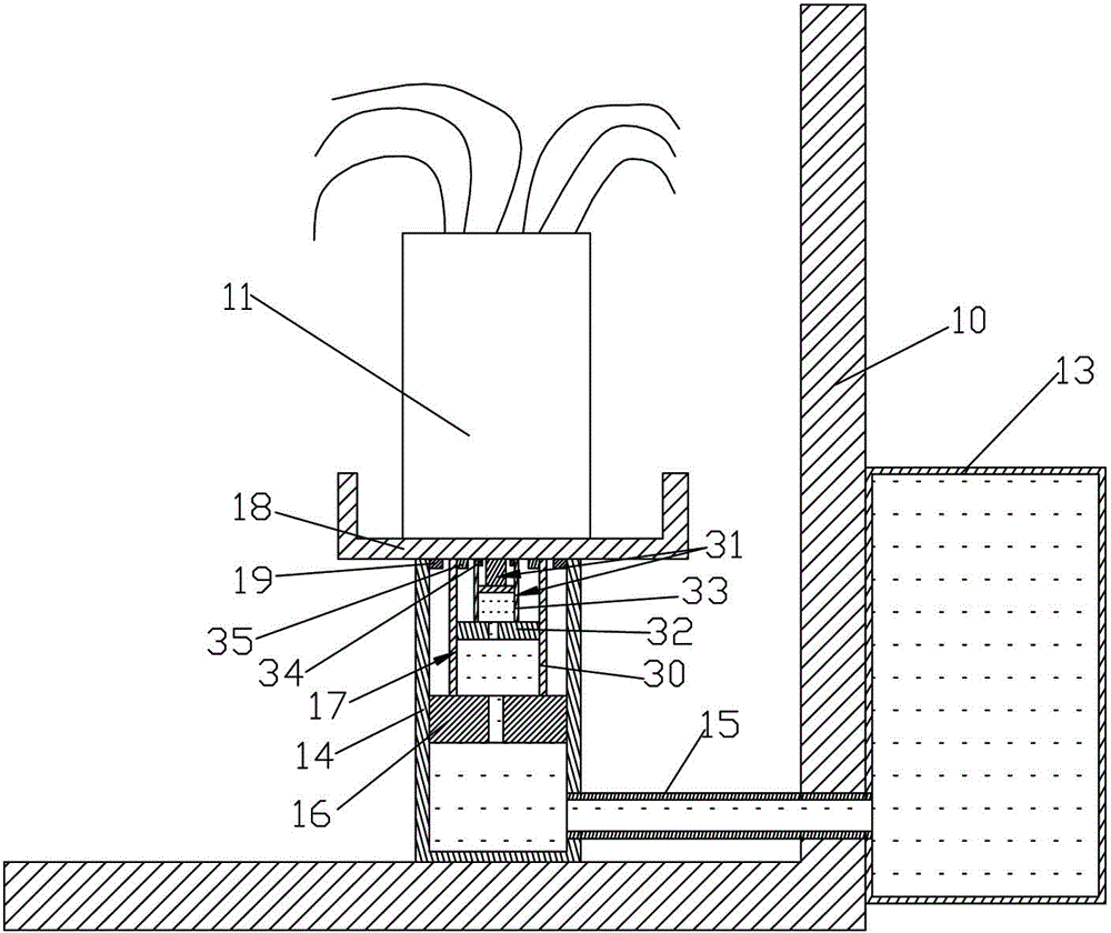
[0032] Such as image 3As shown, the difference between the third embodiment and the first example is that the third embodiment improves the piston rod 17 on the basis of the first embodiment. The piston rod 17 includes a main rod body 30 and two sets of pushing devices 31 . Each group of pushing devices 31 includes a secondary moving piston 32 and a secondary moving rod body 33 connected with the secondary moving piston 32 . All the pushing devices 31 are arranged sequentially from the outside to the inside, the cross-sectional areas of the secondary moving pistons 32 of all the pushing devices 31 decrease successively from the outside to the inside, and the cross-sectional areas of the secondary moving rod bodies 33 corresponding to all the secondary moving pistons 32 are given by From the outside to the inside, the secondary moving piston 32 of the pushing device 31 at the inner level is installed in the secondary moving rod body 33 of the pushing device 31 at the outer le...


PUM


Abstract

The invention relates to a system capable of automatically controlling the height of a flowerpot. The system comprises the flowerpot placed on the inner side of a windowsill wall. The system further comprises a liquid containing barrel and a heat absorbing barrel, wherein the liquid containing barrel is arranged below the flowerpot, the heat absorbing barrel is arranged on the outer side of the windowsill wall, the heat absorbing barrel is communicated with the liquid containing barrel, the heat absorbing barrel and the liquid containing barrel contain liquid, and the heat absorbing barrel can absorb heat of sunlight and enable the liquid in the heat absorbing barrel to absorb heat; a main piston which can move vertically is arranged in the liquid containing barrel and connected with a piston rod, and the piston rod is connected with the bottom of the flowerpot. According to the system, the piston is lifted by means of thermal expansion and cold shrinkage of the liquid, so that the flowerpot is lifted, and normal photosynthesis of plants in the flowerpot is guaranteed.

Description

technical field [0001] The invention relates to a flowerpot, in particular to a system capable of automatically controlling the height of the flowerpot. Background technique [0002] Sunlight is an indispensable source of energy for plant growth. The flower pots are often placed under the windowsill wall, but because the windowsill wall has a certain height, after the sunlight slanted into the window, it cannot be projected into the flowerpots below the window sill wall, causing the plants in the flowerpots to be unable to receive sunlight. Thus affecting the normal photosynthesis of plants. [0003] In order to allow the plants to receive sunlight, it is often necessary to manually move the flower pots of the plants to the position where the sunlight can reach. However, this method of manually moving the flower pots is often not only cumbersome, but also the position of the flower pots is not fixed. , occupying other parts of the room, often affecting the normal work of t...

Claims


Application Information

Patent Timeline
Patent Type & Authority Applications(China)
IPC IPC(8): G05D3/12A01G9/02
Inventor 李向东
Owner SUZHOU JINCHUANG INTERNET TECH CO LTD
Why Eureka
Try Eureka