Eddy current detection device for fuel rod

An eddy current detection and fuel rod technology, which is applied in the field of nuclear power plant detection, can solve the problems of increasing the workload of the inspectors, damage to the health of the inspectors, and increasing the working time, and achieves the effect of saving operation time and difficulty, low noise and reliable movement.

Active Publication Date: 2014-02-05
STATE NUCLEAR POWER PLANT SERVICE
View PDF11 Cites 6 Cited by
  • Summary
  • Abstract
  • Description
  • Claims
  • Application Information

AI Technical Summary

Problems solved by technology

[0003] A key link in damage determination is the need to use a set of eddy current detection devices to detect damage to fuel rods, but the fuel rod detection environment is in a high radioactive area, which puts high requirements on the positioning and installation of eddy current probes
The eddy current detection device currently used has a complex structure, inconvenient manipulation, and low efficiency. The inspectors need to inspect the fuel rods near the reactor, which will cause health damage to the inspectors; There are many rods in the fuel rod, if it is found that the fuel rod needs to be replaced during the inspection, then the eddy current detection device needs to be removed and the fuel rod replacement device is used to replace the problematic fuel rod. The detection and replacement work need to be carried out separately, which will undoubtedly increase The workload of the inspectors will increase the working hours, and the investment will further increase. Therefore, in order to ensure the economy of fuel rod repair and replacement and the reliability of the inspection, the inspectors imagine that the fuel rods are lifted and lowered. detection and can be combined with replacement work, but there is no detection device that can achieve both detection accuracy and detection time

Method used


Image

  • Eddy current detection device for fuel rod
  • Eddy current detection device for fuel rod
  • Eddy current detection device for fuel rod

Examples


Embodiment Construction

[0031] The structures, proportions, sizes, etc. shown in the accompanying drawings of the description are only used to match the content disclosed in the description, for those who are familiar with the technology to understand and read, and are not used to limit the conditions for the implementation of the present invention, so there is no Technically, any modification of structure, change of proportional relationship or adjustment of size shall still fall within the scope of the technical content disclosed in the present invention without affecting the functions and objectives of the present invention. within the range that can be covered. At the same time, terms such as "upper", "lower", "front", "rear", and "middle" quoted in this specification are only for the convenience of description, and are not used to limit the scope of the present invention. , the change or adjustment of its relative relationship, without substantive changes in the technical content, should also be...


PUM


Abstract

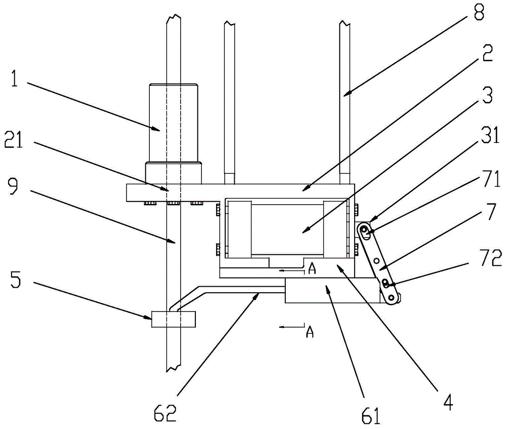
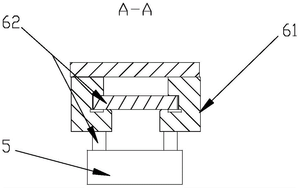
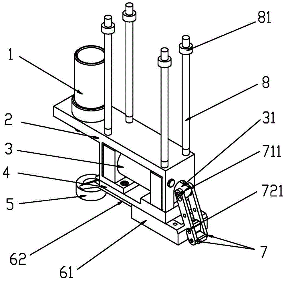
The invention provides an eddy current detection device for a fuel rod. The eddy current detection device for the fuel rod comprises a guide cylinder, an installation plate, a driving device, a telescopic mechanism and an eddy current probe, wherein a through hole is formed in the installation plate; the guide cylinder is arranged at the upper end of the installation plate and is coaxial with the through hole; the driving device is arranged at the lower end of the installation plate and is connected with the telescopic mechanism; a movement direction of the telescopic mechanism is perpendicular to the axis of the guide cylinder and is positioned on the radial extension line of the guide cylinder; the end of the telescopic mechanism is connected with the eddy current probe; under the driving of the telescopic mechanism, the eddy current probe horizontally moves between a working position and a non-working position; when being at the working position, the eddy current probe is coaxial with the guide cylinder. The eddy current detection device for the fuel rod is connected with a fuel rod replacement device through the guide cylinder and can be used for detecting the fuel rod on line on the fuel rod replacement device; if the detected fuel rod is defective, the fuel rod can be directly repaired or replaced, so that the operation time is shortened, and the operation difficulty is reduced; moreover, the eddy current detection device for the fuel rod is reliable to move and high in accuracy.

Description

technical field [0001] The invention relates to the field of nuclear power plant detection, in particular to a fuel rod eddy current detection device. Background technique [0002] A fuel assembly in a nuclear power plant consists of a plurality of fuel rods arranged at regular intervals and fixed in the reactor. The fuel rods are in a state of high temperature, high pressure and high radioactivity for a long time during the operation of the reactor, coupled with the influence of foreign matter in the core, vibration and water flow impact, the fuel rods are prone to damage and leakage, so the fuel rods need to be regularly inspected For damage determination, damaged fuel rods need to be repaired or replaced in time. [0003] A key link in damage determination is to use a set of eddy current detection devices to detect damage to fuel rods, but the fuel rod detection environment is in a high radioactive area, which puts forward high requirements for the positioning and instal...

Claims


Application Information

Patent Timeline
Patent Type & Authority Applications(China)
IPC IPC(8): G21C17/10G21C19/26
CPCY02E30/30
Inventor 许小进李颖曾道英叶琛
Owner STATE NUCLEAR POWER PLANT SERVICE
Why Eureka
Try Eureka