
Movable discharge electrode applied to capillary tube discharge soft X-ray lasers

A discharge electrode and capillary technology, applied in the direction of circuits, electrical components, phonon exciters, etc., can solve problems such as inconsistencies in current waveforms, and achieve accurate laser gain coefficients and accurate measurement effects

Inactive Publication Date: 2014-02-05
HARBIN INST OF TECH
View PDF4 Cites 6 Cited by
  • Summary
  • Abstract
  • Description
  • Claims
  • Application Information

AI Technical Summary

Problems solved by technology

[0005] The present invention aims to solve the problem that the current waveform obtained under different gain medium lengths is inconsistent with the main pulse current waveform in the existing method of changing the gain medium, and now provides a movable discharge capillary discharge soft X-ray laser electrode

Method used


Image

  • Movable discharge electrode applied to capillary tube discharge soft X-ray lasers
  • Movable discharge electrode applied to capillary tube discharge soft X-ray lasers
  • Movable discharge electrode applied to capillary tube discharge soft X-ray lasers

Examples


specific Embodiment approach 1

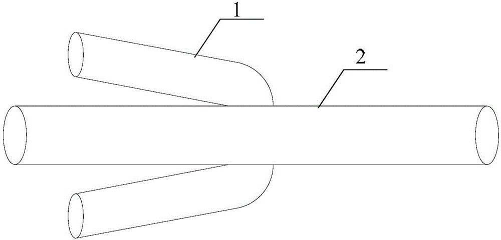
[0018] Specific implementation mode one: refer to figure 1 Specifically explain this embodiment, the movable discharge electrode used in the capillary discharge soft X-ray laser described in this embodiment, which includes: a steel wire 1 and an electrode 2;

[0019] There is a through hole on the electrode 2, the diameter of the through hole is the same as the outer diameter of the steel wire 1, the steel wire 1 passes through the through hole and is fixed on the electrode 2, and the steel wire 1 is perpendicular to the electrode 2, and both ends of the steel wire 1 are bent at the same time to one end of electrode 2;

[0020] The outer diameter of the steel wire 1 is smaller than that of the electrode 2; the average tension of the steel wire 1 is between 88kg and 92kg, and the outer diameter of the steel wire 1 is between 0.8mm and 1.2mm.

[0021] The inner diameter of the capillary 3 is between 8.0 and 3.0 mm, the most common inner diameter being 3.2 mm. The inner diamete...

specific Embodiment approach 2

[0022] Embodiment 2: This embodiment further describes the movable discharge electrode used in the capillary discharge soft X-ray laser described in Embodiment 1. In this embodiment, the electrode 2 is a molybdenum electrode. Embodiment 3: This embodiment further describes the movable discharge electrode used in the capillary discharge soft X-ray laser described in Embodiment 1 or 2. In this embodiment, the length of the electrode 2 is 10 mm.

specific Embodiment approach 4

[0023] Embodiment 4: This embodiment further describes the movable discharge electrode used in the capillary discharge soft X-ray laser described in Embodiment 1 or 2. In this embodiment, the outer diameter of the steel wire 1 is 1 mm.


PUM

PropertyMeasurementUnit
Outer diameteraaaaaaaaaa
Lengthaaaaaaaaaa
Outer diameteraaaaaaaaaa

Abstract

The invention relates to a movable discharge electrode, in particular to a movable discharge electrode applied to capillary tube discharge soft X-ray lasers. The movable discharge electrode aims at solving the problem that in an existing method for changing gain media, current waveforms obtained under the condition of different gain medium lengths are not coincident with a main pulse current waveform, and the inherent thought that in the prior art, the length of a capillary tube is changed or the length of an electrode is changed is eliminated. An elastic steel wire is arranged on the electrode, the effect that the electrode can be fixed at any position in the capillary tube is achieved, and then the aim of changing the gain media is achieved. As when the electrode is fixed at any position in the capillary tube, the total length of a plasma column is the difference of the length of the capillary tube and the length of the electrode, it is guaranteed that the total length of the plasma column is kept unchanged, and then the effect that under the condition of different gain medium lengths, the pulse current waveforms same as the main pulse current waveform are obtained is achieved. The movable discharge electrode is suitable for a capillary tube discharge test.

Description

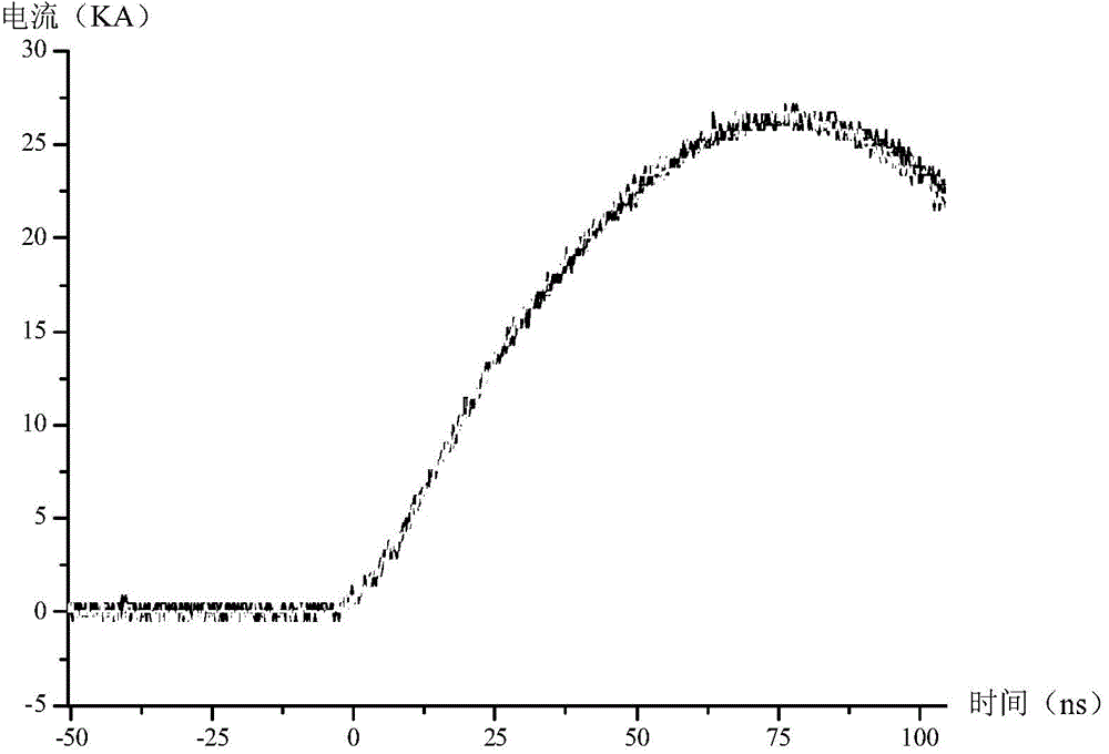
technical field [0001] The invention relates to a movable discharge electrode. Background technique [0002] Capillary discharge soft X-ray laser refers to the use of capillary discharge Z-pinch effect to obtain soft X-ray laser pulses. In the experiment, the main pulse power supply generates the main pulse voltage to discharge the gas in the capillary, and forms a current pulse with an amplitude of tens of thousand amperes in the first half cycle, which is called the main pulse current. Since the half period of the electric pulse is 130ns, a skin effect will be generated when the pre-ionized plasma flows, and the current only flows on the surface of the plasma. Due to the interaction between the discharge current and the magnetic field generated by itself, a Lorentz force pointing to the axis is generated, and the plasma shrinks towards the axis, which is called the Z-pinch effect. During this process, due to the collision of electrons and ions and Joule heating, the temp...

Claims


Application Information

Patent Timeline
IPC IPC(8): H01S4/00
Inventor 赵永蓬姜杉崔怀愈刘涛丁宇洁
Owner HARBIN INST OF TECH
Learn More