

Motor drive circuit with dead band time delay
A technology of motor drive circuit and photoelectric isolation circuit, which is applied in the field of circuits, can solve problems such as low anti-interference ability and direct connection of upper and lower bridge arms, and achieve the effects of strong anti-interference ability, reduced interference, and reduced design difficulty and burden
- Summary
- Abstract
- Description
- Claims
- Application Information
AI Technical Summary
Problems solved by technology
Method used
Image

Examples
Embodiment Construction
[0023] The present invention will be further described below in conjunction with the accompanying drawings. The following examples are only used to illustrate the technical solution of the present invention more clearly, but not to limit the protection scope of the present invention.
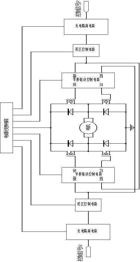
[0024] The motor drive circuit with dead zone delay of the present invention mainly includes a photoelectric isolation circuit, a dead zone delay control circuit, a half bridge drive control circuit, an H bridge drive circuit and a power conversion circuit, and its principle block diagram is as follows figure 1 shown.
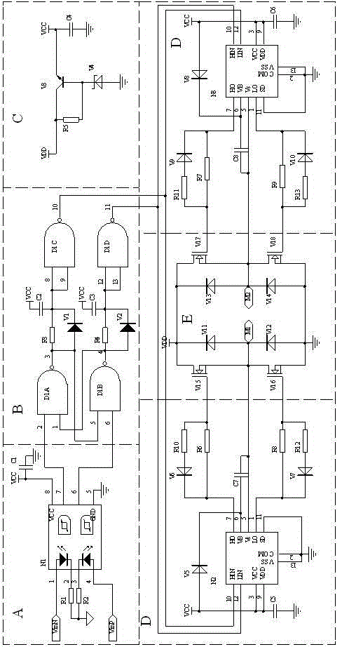
[0025] The specific circuit diagram of each part is as follows figure 2 As shown in the figure, VinN and VinP are two input control signals, and terminals M1 and M2 are respectively connected to the two ends of the motor. The principle of each part of the circuit is as follows:
[0026] Part A is a photoelectric isolation circuit, using a dual-channel high-speed photocoupler ...
PUM
 Abstract
Description
Claims
Application Information