Bipolar trigger type multi-rod-electrode vacuum trigger switch

A trigger switch, multi-rod technology, applied in the direction of electronic switches, electrical components, pulse technology, etc., can solve the problems of lower power frequency breakdown voltage, difficulty in stable triggering of switches, and shortened ablation life of switches, etc., to achieve uniform electric field , reduce ablation, high flow capacity effect

Active Publication Date: 2014-02-05
HUAZHONG UNIV OF SCI & TECH +1
View PDF3 Cites 3 Cited by
  • Summary
  • Abstract
  • Description
  • Claims
  • Application Information

AI Technical Summary

Problems solved by technology

[0003] At present, when the traditional unipolar vacuum trigger switch (the default trigger pole is located in the center of the cathode) is used in the power system, there are mainly the following problems: (1) When the two ends of the main gap of the switch are positive half waves, the switch can be triggered stably, while When the two ends of the main gap of the switch are negative half-waves, the switch is difficult to trigger stably; (2) After the switch is turned off, the two ends of the main electrode are ablated, which reduces the power frequency breakdown voltage, which makes the switch prone to self-breakdown; ( 3) Since only one trigger electrode is involved in the work, the deposition of metal vapor will short-circuit along the surface when the main gap is turned on, so that it cannot be triggered normally, and the life of the trigger electrode will be shortened; (4) due to the initial plasma generated when the trigger electrode is triggered The diffusion process of the switch is limited by the internal electric field of the switch, and the ablation of the main electrode of the switch is often concentrated in the area with the highest initial plasma concentration, so the life of the switch will be shortened due to the ablation of the main electrode

Method used


Image

  • Bipolar trigger type multi-rod-electrode vacuum trigger switch
  • Bipolar trigger type multi-rod-electrode vacuum trigger switch
  • Bipolar trigger type multi-rod-electrode vacuum trigger switch

Examples


Embodiment Construction

[0023] In order to make the object, technical solution and advantages of the present invention clearer, the present invention will be further described in detail below in conjunction with the accompanying drawings and embodiments. It should be understood that the specific embodiments described here are only used to explain the present invention, not to limit the present invention. In addition, the technical features involved in the various embodiments of the present invention described below can be combined with each other as long as they do not constitute a conflict with each other.

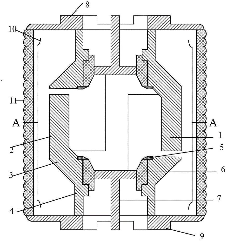
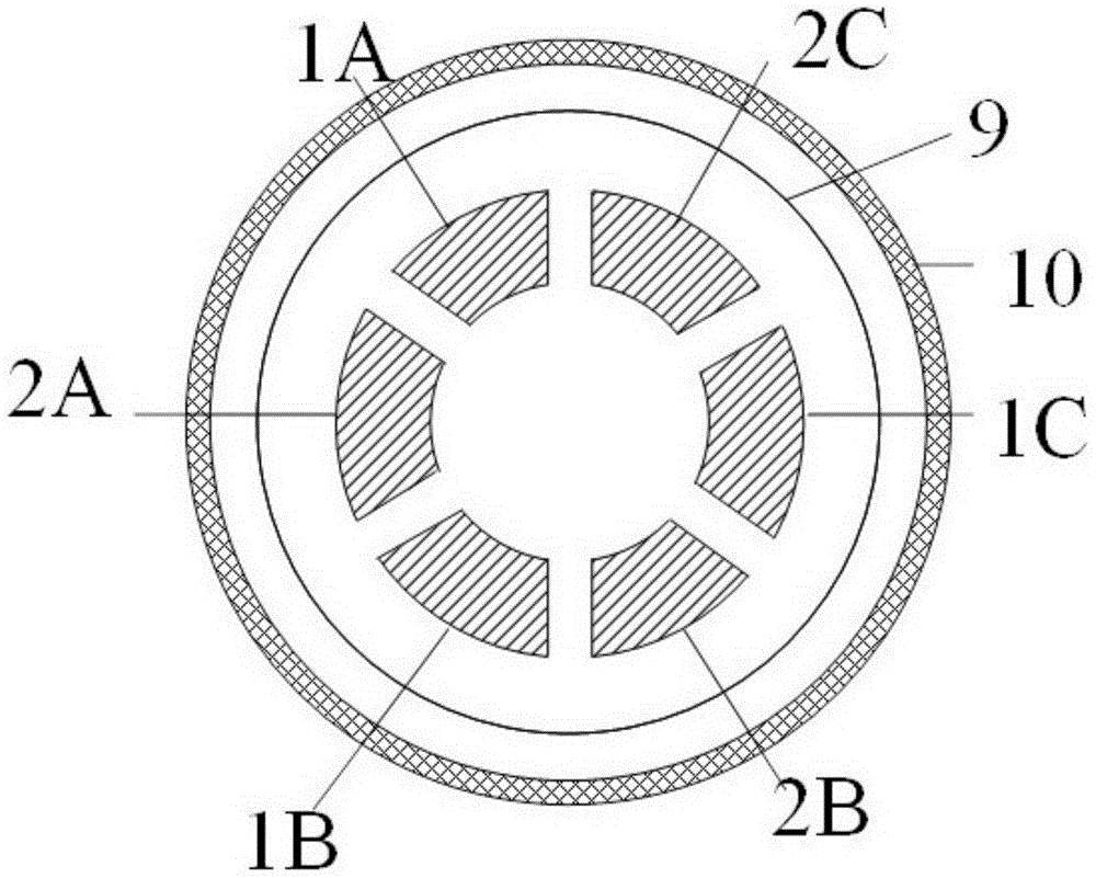
[0024] Such as figure 1 As shown, the bipolar trigger type multi-rod vacuum trigger switch according to the embodiment of the present invention includes an airtight casing and a shield 10 arranged on the inner wall of the airtight casing. The airtight casing is composed of an insulating casing 11 and a cathode flange 8 and an anode flange 9 arranged at both ends of the insulating casing 11. The...


PUM


Abstract

The invention discloses a bipolar trigger type multi-rod-electrode vacuum trigger switch which comprises a sealed shell body, wherein the sealed shell body is formed by an insulation outer shell, a cathode flange and an anode flange, and the cathode flange and the anode flange are arranged at the two ends of the insulation outer shell; a cathode and an anode are arranged at the two ends of the sealed shell body respectively, the cathode and anode have the same structure and are respectively provided with an electrode bottom column, an electrode platform and multiple rod-shaped electrodes arranged on the electrode platform; the rod-shaped electrodes of the cathode and rod-shaped electrodes of the anode extend in opposite directions and are arranged in a staggered mode, the widths of gaps between the adjacent rod-shaped electrodes are the same, and the widths of the gaps are the same as the widths from top ends of the rod-shaped electrodes to the opposite electrode platforms; a cathode trigger structure and an anode trigger structure are arranged in the cathode and the anode respectively. The switch can be stably triggered regardless of the polarity of voltage of main gaps, application requirements under power frequency voltage of an electric power system can be met, through-current capability is higher, the service life is longer, and self-breakdown does not easily occur.

Description

technical field [0001] The invention belongs to the technical field of pulse power, and more specifically relates to a bipolar trigger type multi-rod vacuum trigger switch. Background technique [0002] The vacuum trigger switch is a closed switch that uses vacuum as the main gap insulation and arc extinguishing medium, and provides a trigger signal through an external trigger circuit to control conduction. The trigger mode of the vacuum switch is often unipolar trigger, that is, the trigger pole and the cathode are installed together. This is because the vacuum trigger switch is mainly used in the pulse power system, and the voltage applied to the main electrode of the switch is generally unipolar. There are two positive and negative half-waves in the power frequency voltage of the system, so the vacuum trigger switch is rarely used in the power system. [0003] At present, when the traditional unipolar vacuum trigger switch (the default trigger pole is located in the cent...

Claims


Application Information

Patent Timeline
Patent Type & Authority Applications(China)
IPC IPC(8): H03K17/54
Inventor 戴玲林福昌姚星辰王延召张弛
Owner HUAZHONG UNIV OF SCI & TECH
Why Eureka
Try Eureka