
Transmission unit with planetary gear transmission

A technology for planetary gears and transmissions, applied to belts/chains/gears, vehicle gearboxes, bicycle accessories, etc., which can solve the problems of hindering the tooth meshing of planetary gear transmissions, unrealizable deployment length, high energy consumption, etc.

Active Publication Date: 2016-10-26
卡斯滕·贝廷
View PDF7 Cites 0 Cited by
  • Summary
  • Abstract
  • Description
  • Claims
  • Application Information

AI Technical Summary

Problems solved by technology

[0011] Solution a. has the disadvantage that due to the different arrangement of the drive sprocket (outside) and driven sprocket (inside) relative to the bicycle frame, the bicycle frame must be guided between the sprockets or through the chain drive
There is thus an additional disadvantage: the achievable overall gear ratios for wheel sizes smaller than 14 inches hardly allow for a suitable spread length
The high rotational speeds generated by the second chain drive require high energy consumption
The resulting disadvantage is that the torque of the driven ring gear first has to be transmitted to the rear wheel axle before it can be received by the planetary carrier on the other side of the bicycle frame
Another disadvantage is that the bending moments acting on the rear axle due to the weight of the cyclist also act on the planet carrier in the disclosed solution and prevent the tooth meshing of the planetary transmission
In addition, only one shift gear of the planetary transmission can be realized when the planetary transmission is arranged on the inner side of the bicycle frame, because since the driven sun gear is arranged as the sun gear supported on the rear wheel From the perspective of the wheels, torque transmission can only be carried out axially to the rear wheels

Method used


Image

  • Transmission unit with planetary gear transmission
  • Transmission unit with planetary gear transmission
  • Transmission unit with planetary gear transmission

Examples


Embodiment approach

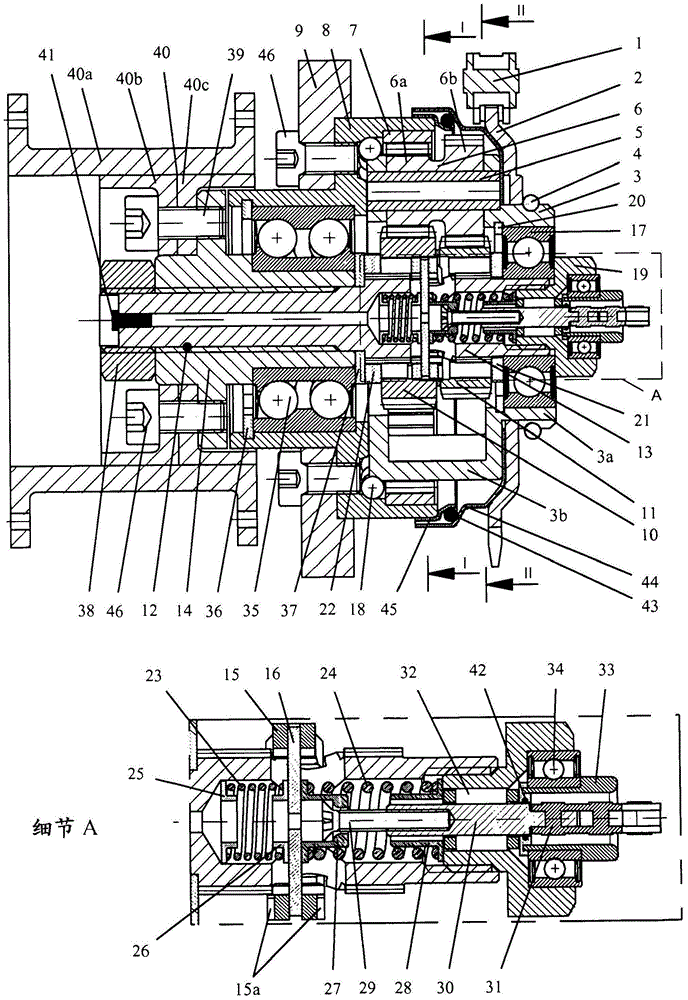
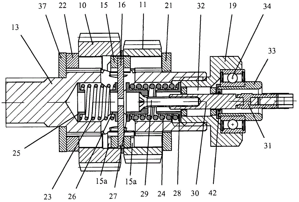
[0043] figure 1 Shown is a sectional view of a two-speed transmission unit with a spur-dog-freewheel clutch and a single-arm rear wheel suspension.

[0044] V-belts or toothed belts connected to a continuous chain drive or a continuous belt drive preceding a variator unit or connected to a spur gear drive preceding a variator unit, shown either by a chain 1 or not separately or not separately The driven wheel 2 driven by the spur gear is operatively connected in relative rotation to the drive 3 of the transmission unit via a shaft-hub connection, wherein the driven wheel 2 is fastened to the drive 3 , for example by means of a safety ring 4 . The driver 3 driven by the driven wheel 2 comprises a driver part 3a and is formed as a planetary carrier 3b of a planetary gearing, viewed axially towards the bicycle frame, according to a particular feature of the invention.

[0045] According to a particular feature of the invention, the driven wheel 2 and the planetary carrier 3b are...


PUM


Abstract

The invention relates to a transmission unit with a planetary gear transmission, optionally for a bicycle or for a bicycle trailer. The transmission unit developed to drive the small size rear wheels consists of: a planetary transmission with an internal gear (7) connected to the bicycle frame (9), a planetary carrier (3b) with planetary gears (6a, 6b) and One or two sun gears (10, 11); rear axle (12) coaxial with said sun gear or rear axle with said sun gear; drive coupled to planetary carrier or shaped as planetary carrier (3b ) of the drive (3). It is characterized in that the bearing (35) supports the rear wheel shaft (12) on the inner side relative to the bicycle frame (9) in the radial direction and is between the support of the rear wheel (40) and the planetary gear transmission in the axial view, the planet The gear transmission is in turn located on the same side of the bicycle frame as the front transmission, for example the chain drive ( 1 , 2 ). In this way, a belt drive at the front, a short distance between the rear wheel and the pedal bearing and a single-arm suspension in the bike rack are possible. The transmission unit provides one or two gear ratios.

Description

technical field [0001] The invention relates to a transmission unit with a planetary transmission, optionally for a bicycle with small wheels or for a bicycle trailer. Background technique [0002] The chain drive is the most popular bicycle drive. In this case, the driving sprocket connected to the pedal is mainly located outside the bicycle frame when viewed axially, and the driven ring gear supported on the rear wheel shaft is mainly arranged inside the bicycle frame and the bicycle frame when viewed axially. between the rear wheels. [0003] Multi-speed shifting for bicycles is preferably via a chain drive with different sprockets on the pedals and a different ring gear on the rear wheel or by a single-stage chain drive combined with a hub shift in the rear wheel or by both A combination of schemes can be realized. This results in a total transmission ratio of up to 1:4.9 (eg SRAMi-motion with chainring combination 48 / 18). These shifting combinations are applied to w...

Claims


Application Information

Patent Timeline
Patent Type & Authority Patents(China)
IPC IPC(8): B62K25/00B62M11/16
CPCB62K25/005B62M11/16B62M11/02F16H37/04B62K25/00
Inventor 卡斯滕·贝廷
Owner 卡斯滕·贝廷
Learn More