Automatic wire feeding system of automatic laser welding machine

A laser welding machine and wire feeding system technology, applied in laser welding equipment, welding equipment, metal processing equipment, etc., can solve problems such as low efficiency, high weld depth-to-width ratio, affecting welding quality and efficiency, and avoid time-consuming Laborious and inaccurate, increase the scope of application, and save labor costs

Inactive Publication Date: 2014-02-12
SHENZHEN TONGFA LASER EQUIP
View PDF10 Cites 13 Cited by
  • Summary
  • Abstract
  • Description
  • Claims
  • Application Information

AI Technical Summary

Problems solved by technology

The current laser welding is mainly used for welding thin-walled materials or precision parts, and can be used for various butt welding, sealing welding, spot welding, lap welding, etc. The influence area is small, the deformation is small, the welding speed is fast, the weld seam is smooth and beautiful, no need to deal with after welding or only simple treatment is required, the weld seam quality is high, no pores will be generated, and the laser focus spot is small, so it can be accurately Control the accuracy of positioning, the position of laser light irradiation is easy to control, so it is easy to realize welding automation. At present, in the process of laser welding, the welding wire is delivered manually, because the process of manual delivery requires a high concentration of human attention and requires Adjusting the speed and strength of welding wire delivery requires workers to master skilled skills and manual delivery of welding wire, which is inefficient; therefore, it will not only increase the cost of manpower but also affect the quality and efficiency of welding, which has become a key to improving the efficiency and quality of laser welding item puzzle

Method used


Image

  • Automatic wire feeding system of automatic laser welding machine
  • Automatic wire feeding system of automatic laser welding machine

Examples


Embodiment Construction

[0014] The present invention will be described in further detail below in conjunction with the accompanying drawings.

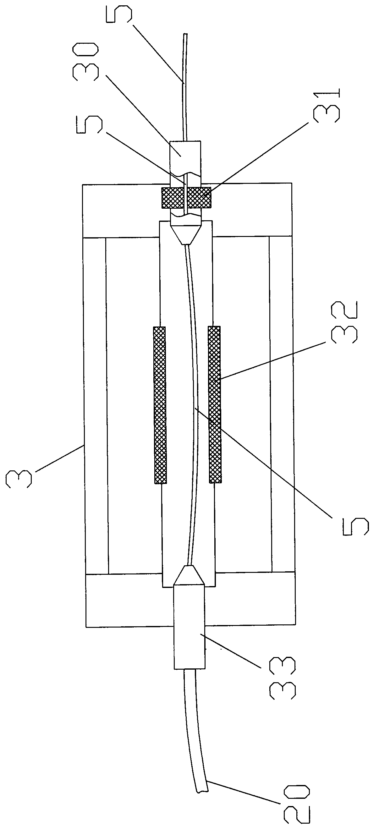
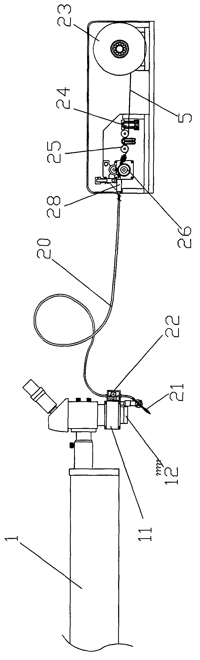
[0015] Such as figure 1 As shown, in order to achieve the above object, the automatic wire feeding system of the automatic laser welding machine used in conjunction with the laser head 12 of the present invention includes successively a welding wire cylinder 23 with a winding welding wire 5, a welding wire guide for guiding the welding wire Mechanism 24, welding wire straightening mechanism 25, blowing wire feeding device, terminal wire feeding speed control mechanism 22 for precisely controlling the wire feeding speed, and the above-mentioned welding wire guiding mechanism, welding wire straightening mechanism, blowing wire feeding device It is connected with the wire feeding speed control mechanism at the end and controls the driving unit for controlling its operating speed. The blowing wire feeding device is provided with a wire blowing tube 20 for blowing...


PUM


Abstract

The invention relates to an automatic wire feeding system of an automatic laser welding machine. The automatic wire feeding system is matched with a laser head for use. The automatic wire feeding system of the automatic laser welding machine comprises a welding wire drum, a welding wire correcting mechanism, a welding wire straightening mechanism, an air blowing and wire feeding device, a tail end wire feeding speed control mechanism and a control driving unit in sequence, wherein the welding wire drum is provided with a wound welding wire, the welding wire correcting mechanism is used for correcting the welding wire, the tail end wire feeding speed control mechanism is used for precisely controlling the wire feeding speed, the control driving unit is connected with the welding wire correcting mechanism, the welding wire straightening mechanism, the air blowing and wire feeding device and the tail end wire feeding speed control mechanism and is used for controlling the speed, the air blowing and wire feeding device is provided with a wire blowing pipe used for blowing and feeding the welding wire and is connected with a wire feeding hole of the wire blowing pipe, the tail end of the wire blowing pipe is provided with a welding wire outlet end which is fixedly connected with an end laser head, and the port axis of the welding wire outlet end penetrates through a laser condensation welding focus on the optical axis of the laser head. The automatic wire feeding system can be used for automatically conveying the welding wire to a welding point, and operating personnel do not need to convey the welding wire by hand, so that the condition that time and effort are consumed due to the fact that the welding wire is manually and imprecisely conveyed is avoided, the labor cost is reduced, the welding quality is conveniently ensured, and the application range of the laser welding machine is enlarged.

Description

technical field [0001] The field relates to a wire feeding system of a laser welding machine, in particular to an automatic wire feeding system used in various laser welding machines. Background technique [0002] Laser welding is a new type of welding processing method. It uses high-energy laser pulses to locally heat the small area of ​​the processed material. The heat generated by the powerful laser radiation energy will melt the material at the welding position, and the material will form a specific after melting. The molten pool is used to achieve the purpose of laser welding. The current laser welding is mainly used for welding thin-walled materials or precision parts, and can be used for various butt welding, sealing welding, spot welding, lap welding, etc. The influence area is small, the deformation is small, the welding speed is fast, the weld seam is smooth and beautiful, no need to deal with after welding or only simple treatment is required, the weld seam quali...

Claims


Application Information

Patent Timeline
Patent Type & Authority Applications(China)
IPC IPC(8): B23K26/21B23K26/70
CPCB23K26/211B23K26/702
Inventor 王小峰
Owner SHENZHEN TONGFA LASER EQUIP
Why Eureka
Try Eureka