Hydraulic auxiliary coupler loop of backhoe loader

A backhoe loader and hydraulic technology, which is applied to mechanically driven excavators/dredgers, mechanical equipment, fluid pressure actuating devices, etc., can solve problems such as many faults, high cost, and complex hydraulic system of the whole machine, and achieve improvement The effect of reliability, compact structure, and simplified complexity

Inactive Publication Date: 2014-02-12
JIANGSU LIUGONG MACHINERY
View PDF4 Cites 3 Cited by
  • Summary
  • Abstract
  • Description
  • Claims
  • Application Information

AI Technical Summary

Problems solved by technology

[0002] With the development of technology, the functions of backhoe loaders are becoming more and more diversified. To realize the multi-function of backhoe loaders, various attachments, such as cleaners, milling machines, breakers, etc., must be used. The power source of the tool is generally the hydraulic system of the whole machine. Generally, the hydraulic system of the whole machine will set up an auxiliary joint to provide power for the attachment. The backhoe loader includes a loading end and an excavating end, which can realize both loading and excavation operations. There are many functional links of the main control valve required for each action, and auxiliary links for attachments are required, which makes the hydraulic system of the whole machine more complicated, costly, and has many failures

Method used


Image

  • Hydraulic auxiliary coupler loop of backhoe loader
  • Hydraulic auxiliary coupler loop of backhoe loader
  • Hydraulic auxiliary coupler loop of backhoe loader

Examples


Embodiment 1

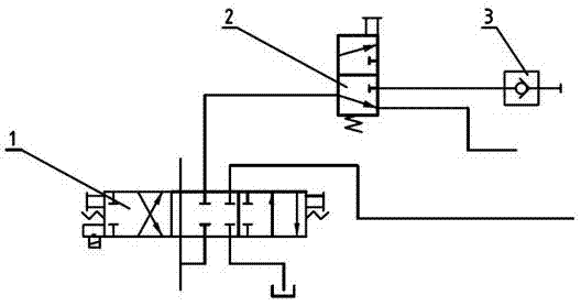
[0015] Such as figure 1 As shown, a backhoe loader hydraulic auxiliary circuit includes a main control valve 1, the main control valve 1 is a three-position six-way reversing valve, and a switching valve 2, and the switching valve 2 is a two-position three-way One of the working oil lines of the main control valve 2 is provided with the switching valve 2 , and the end of the working oil line of the switching valve 2 is also provided with a quick connector 3 .

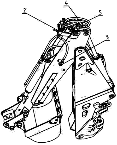
[0016] Such as image 3 As shown, the switching valve 2 is set on the arm of the excavating arm through a support, the oil inlet of the switching valve 2 is connected to the working pipeline 4 of the main control valve, and the two working oils of the switching valve 2 The roads are respectively connected to the quick joint 3 and the oil inlet of the telescopic oil cylinder 5.

Embodiment 2

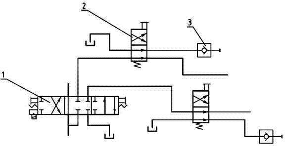
[0018] Such as figure 2 As shown, a backhoe loader hydraulic auxiliary circuit includes a main control valve 1, the main control valve 1 is a three-position six-way reversing valve, and a switching valve 2, and the switching valve 2 is a two-position four-way The switching valve 2 is arranged on the working oil circuit of the main control valve 2, the oil return circuit of the switching valve 2 is connected to the oil tank, and the working oil circuit end of the switching valve 2 is also provided with a quick joint 3.


PUM


Abstract

The invention discloses a hydraulic auxiliary coupler loop of a backhoe loader. The hydraulic auxiliary coupler loop comprises a main control valve and a switching valve, wherein the main control valve is a three-position six-way reversing valve; the switching valve is arranged on a working oil line of the main control valve; and a quick joint is arranged at the tail end of the working oil line of switching valve. The working oil line of the main control valve can be divided into two oil lines through the switching valve, the principle of the switching valve is simple, the structure can be generally manufactured to be small and exquisite, and the arrangement is convenient, so that the complexity of a hydraulic system can be greatly simplified in an arrangement process of the whole hydraulic pipeline of a complete machine, the reliability of the system is improved, and requirements of connecting accessories can be met at the same time.

Description

technical field [0001] The invention relates to a hydraulic auxiliary circuit of an excavating loader, which belongs to the technical field of engineering machinery. Background technique [0002] With the development of technology, the functions of backhoe loaders are becoming more and more diversified. To realize the multi-function of backhoe loaders, various attachments, such as cleaners, milling machines, breakers, etc., must be used. The power source of the tool is generally the hydraulic system of the whole machine. Generally, the hydraulic system of the whole machine will set up an auxiliary joint to provide power for the attachment. The backhoe loader includes a loading end and an excavating end, which can realize both loading and excavation operations. There are many functional links of the main control valve required for each action, and auxiliary links for attachments are required, which makes the hydraulic system of the whole machine more complicated, costly, and ...

Claims


Application Information

Patent Timeline
IPC IPC(8): E02F3/42F15B13/02
Inventor 陈晋市刘寅贾志伟王宇婷吴艳泽尚瑞龚勋
Owner JIANGSU LIUGONG MACHINERY
Why Eureka
Try Eureka