Controllable drop point safety impact grab

A safe impact and controllable technology, applied in the direction of mechanically driven excavators/dredgers, etc., to ensure the reliability of clamping and overcome the effects of using defects

Active Publication Date: 2016-08-03
SHANGHAI JINTAI ENG MACHINERY
View PDF7 Cites 0 Cited by
  • Summary
  • Abstract
  • Description
  • Claims
  • Application Information

AI Technical Summary

Problems solved by technology

[0003] The purpose of the present invention is to overcome the defects of the existing traditional impact grab and provide a controllable landing point safety impact grab with guiding facilities and a double suspension fixing mechanism

Method used


Image

  • Controllable drop point safety impact grab
  • Controllable drop point safety impact grab
  • Controllable drop point safety impact grab

Examples


Embodiment Construction

[0017] The present invention is further illustrated below by specific examples.

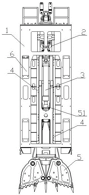
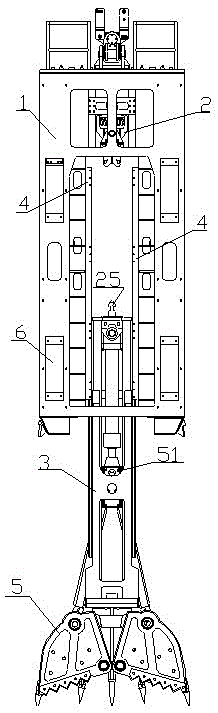
[0018] Such as figure 1 As shown, a safety impact grab with controllable landing point includes a hydraulically controlled opening and closing grab bucket 5, which is characterized in that it also includes a clamping mechanism 2, a frame 1 and a guide column 3,

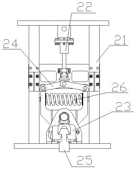
[0019] The clamping mechanism 2 includes an oil cylinder 22, a support 21, a collet 25, two connecting rods 24, two clamp arms 23 and a spring 26; the support 21 includes two side plates and positioning plates symmetrically arranged on the sides of the two side plates, The locating plate is provided with chute symmetrically; two connecting rods 24 have one end connected with the telescopic end pin of the oil cylinder 22, the telescopic end of the oil cylinder 22 is located in the chute of the bracket 21, the other end of the two connecting rods 24 They are respectively connected with the pin shafts at the top of the two clamp arms 23, a...


PUM


Abstract

The invention relates to the field of underground construction equipment, in particular to a safety impact grab with controllable drop point; The mechanism is located at the top of the frame, the frame is hollow inside and has a guide slide rail, the guide column is set in the frame and transitionally fits with the guide slide rail, the grab is set at the end of the guide column, and the guide column is clamped by the clamping mechanism through the chuck fixed. The present invention adopts the above-mentioned design, and the use of guide rails in conjunction with guide columns makes the falling direction of the impact grab predictable. At the same time, the special clamping mechanism has double clamping functions, ensuring the clamping reliability of the impact grab , thereby overcoming the use defects existing in the existing traditional impact grab.

Description

technical field [0001] The invention relates to the field of underground construction equipment, in particular to a controllable landing point safety impact grab. Background technique [0002] Traditional impact grabs are usually suspended and fixed by wire ropes. When in use, let them fall naturally without any guiding facilities. When they fall naturally, they may deviate from the target point, resulting in low construction efficiency. At the same time, because there are no guiding facilities, The impact grab may also pose a safety hazard to surrounding operators when it falls. In addition, there is an obvious potential safety hazard if the impact grab is only suspended by a steel wire rope, that is, once there is a problem with the wire rope, the impact grab is very likely to fall off accidentally. Contents of the invention [0003] The object of the present invention is to overcome the defects of the existing traditional impact grab, and provide a controllable landing...

Claims


Application Information

Patent Timeline
Patent Type & Authority Patents(China)
IPC IPC(8): E02F3/60
Inventor 林坚梁社安
Owner SHANGHAI JINTAI ENG MACHINERY
Why Eureka
Try Eureka