Compressor

A technology for a compressor and a compression mechanism, applied in the field of compressors, can solve the problems of increased volume, complicated structure of scroll compressors, and increased cost of compressors, and achieves the effect of saving design and manufacturing costs

Active Publication Date: 2014-02-12
EMERSON CLIMATE TECH (SUZHOU) CO LTD
View PDF6 Cites 8 Cited by
  • Summary
  • Abstract
  • Description
  • Claims
  • Application Information

AI Technical Summary

Problems solved by technology

[0006] However, the above-mentioned scroll compressor with capacity modulation function is relatively complex in structure, thus resulting in increased cost and increased volume of the compressor

Method used


Image

  • Compressor
  • Compressor
  • Compressor

Examples


Embodiment Construction

[0036] The following description is merely exemplary in nature and is not intended to limit the disclosure, application and uses. It should be understood that throughout the drawings, corresponding reference numerals indicate like or corresponding parts and features.

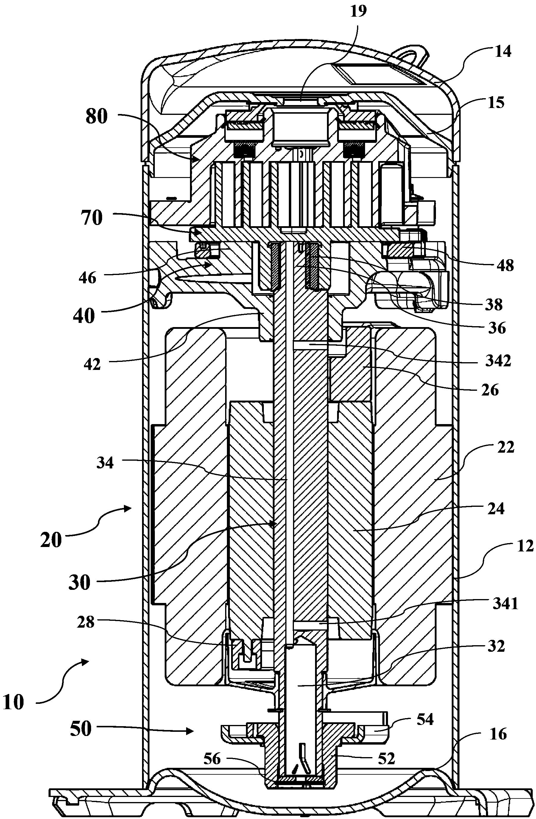
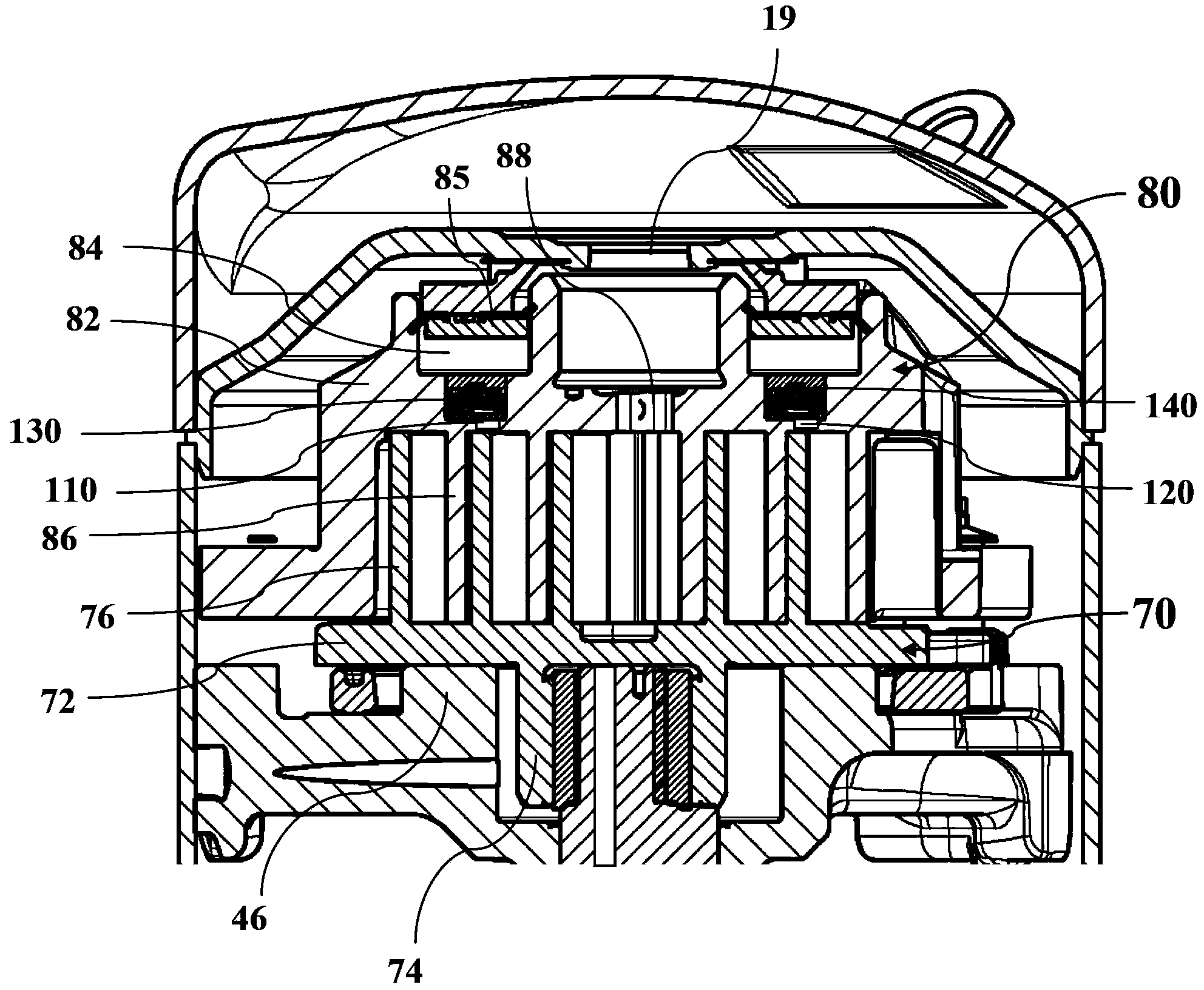
[0037] The following will refer to figure 1 with figure 2 The basic configuration and principle of the scroll compressor 10 according to the first embodiment of the present disclosure will be described.

[0038] Such as figure 1 As mentioned above, the scroll compressor (hereinafter also referred to as compressor) 10 generally includes a substantially cylindrical housing 12, a top cover 14 disposed at one end of the housing 12, and a bottom disposed at the other end of the housing 12. A cover 16 and a partition plate 15 provided between the top cover 14 and the casing 12 to divide the internal space of the compressor into a high pressure side (ie, discharge pressure area) and a low pressure side (suction press...


PUM


Abstract

A disclosed compressor (10) comprises: a shell (12) in which an inspiratory pressure zone and an exhaust pressure zone are defined, and a compression mechanism arranged in the shell; and the compression mechanism comprises: a first vortex part (80) comprising a first end plate (82) and a first vortex blade (86), a second vortex part (70) comprising a second end plate (72) and a second vortex blade (76), a first communication channel (110) which is arranged between a first compression chamber (C1) and the inspiratory pressure zone and selectively provides fluid communication, and a first control valve (150). When the first control valve closes the first communication channel, the compressor works with full capacity, and when the first valve opens the first communication channel, the compressor works with reduced capacity. The compressor provided by the invention helps to realize capacity adjusting of compressors by employing a relatively simple manner.

Description

technical field [0001] The present invention relates to a compressor, more particularly to a scroll compressor with capacity modulation function. Background technique [0002] The statements in this section merely provide background information related to the present disclosure and may not constitute prior art. [0003] A scroll compressor generally includes a fixed scroll member and an orbiting scroll member. The fixed scroll member and the movable scroll member respectively include an end plate and a scroll vane formed on the end plate. The scroll blades of the fixed scroll member and the orbiting scroll member engage with each other to form a series of compression pockets therebetween. When the movable scroll is driven to rotate in translation relative to the fixed scroll (that is, the central axis of the movable scroll rotates around the central axis of the fixed scroll, but the movable scroll itself does not rotate around its own central axis) When rotating), the vol...

Claims


Application Information

Patent Timeline
Patent Type & Authority Applications(China)
IPC IPC(8): F04C18/02F04C28/18
Inventor 孙庆丰慎世珍束宏飞
Owner EMERSON CLIMATE TECH (SUZHOU) CO LTD
Why Eureka
Try Eureka