High-reliability clutch mechanism

A technology of clutch mechanism and reliability, which is applied in the field of high reliability clutch mechanism, can solve the problems that the pawl cannot be pulled back in time, the work reliability, poor stability, and the driving force of the driving wheel cannot be transmitted, so as to achieve friction reduction, The effect of high working reliability and simple structure

Inactive Publication Date: 2014-02-12
马骥 +1
View PDF5 Cites 4 Cited by
  • Summary
  • Abstract
  • Description
  • Claims
  • Application Information

AI Technical Summary

Problems solved by technology

Because the pawl and each tooth groove on the ratchet wheel are always single-point line contact push-up cooperation, and the pawl slides to the next adjacent tooth groove after pushing a tooth groove on the ratchet wheel, the ratchet is always in the same position. Stop sliding and push the top, because the pawl is pulled by the tension spring, the uninterrupted sliding of different amplitudes is easy to deform the tension spring and lose its proper elasticity, resulting in the pawl not being pulled back in time. As a result, it cannot be pushed into the tooth grooves on the ratchet in turn as expected, resulting in slippage of the pusher, work failure, and failure to transmit the driving force of the driving wheel. Therefore, its disadvantages are that it is prone to failure, poor reliability and stability of work
The clutches of motor vehicles mostly use the clutch structure that relies on the friction force of the clutch plate, that is, the friction plate to push the driven wheel, so as to transmit the driving force of the driving wheel. Due to the large friction surface of the friction plate, repeated use will make it wear out quickly , and there will also be local slippage, which will affect the reliability of its work. Therefore, its disadvantage is that the driving force transmission part, that is, the friction plate, is easy to wear, and the work reliability will also be affected to a certain extent.

Method used


Image

  • High-reliability clutch mechanism
  • High-reliability clutch mechanism
  • High-reliability clutch mechanism

Examples


Embodiment 1

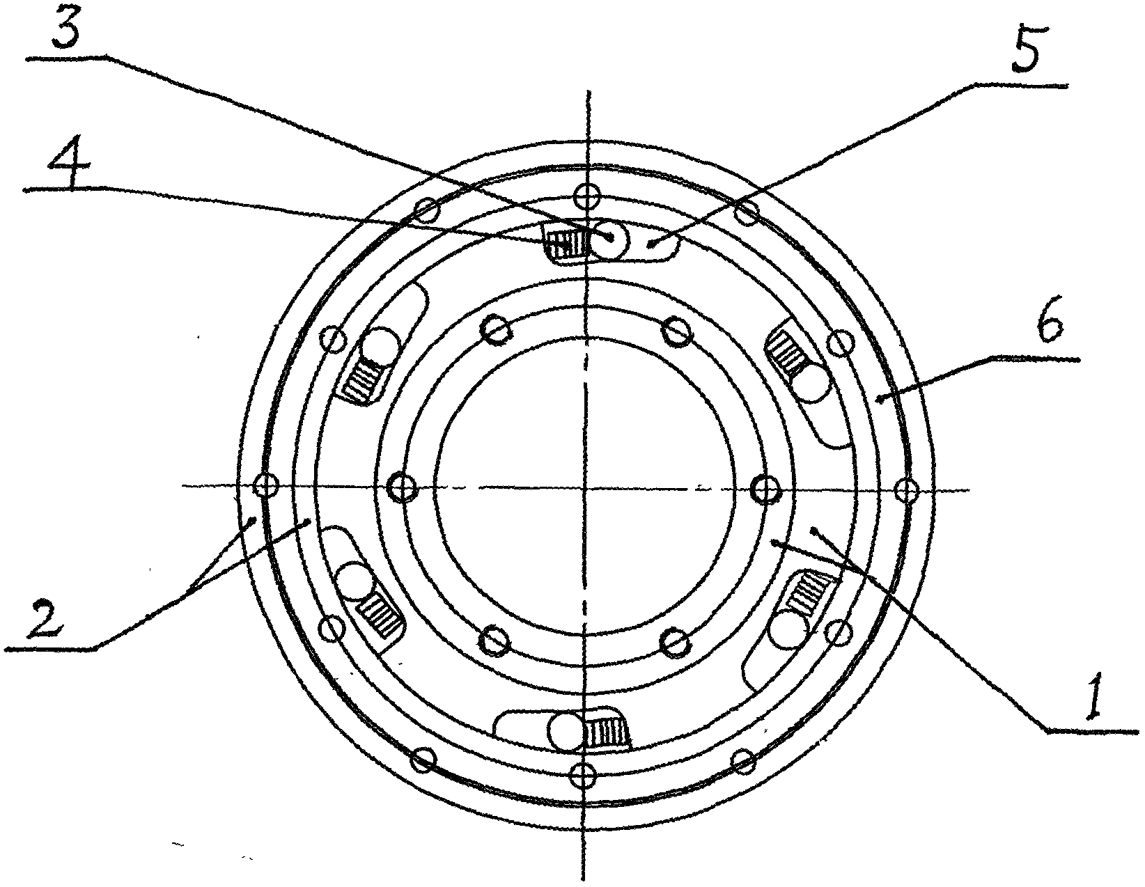
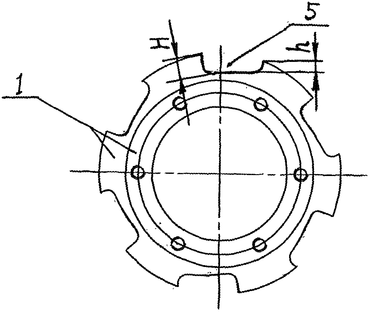
[0023] Example 1, in figure 1 In the schematic diagram shown in the structure, the present invention includes an inner shaft sleeve 1, an outer ring 2 arranged on its periphery, and 6 transmission parts that transmit the rotational force of the inner shaft sleeve 1 to the outer ring 2, and the inner shaft sleeve The outer edge of 1 is provided with 6 wedge-shaped grooves. The above-mentioned wedge-shaped grooves are special-shaped grooves that are deep at one end and shallow at the other end along the circumferential direction of the inner sleeve 1. figure 1 and figure 2In the schematic diagram shown, the wedge-shaped groove 5 is one of the above-mentioned six wedge-shaped grooves, the depth H of the front groove of each of the above-mentioned wedge-shaped grooves is greater than the depth h of the end groove, and is wedge-shaped, and the above-mentioned six wedge-shaped grooves are evenly arranged inside At the outer edge of the shaft sleeve 1, the above-mentioned 6 transmi...

Embodiment 2

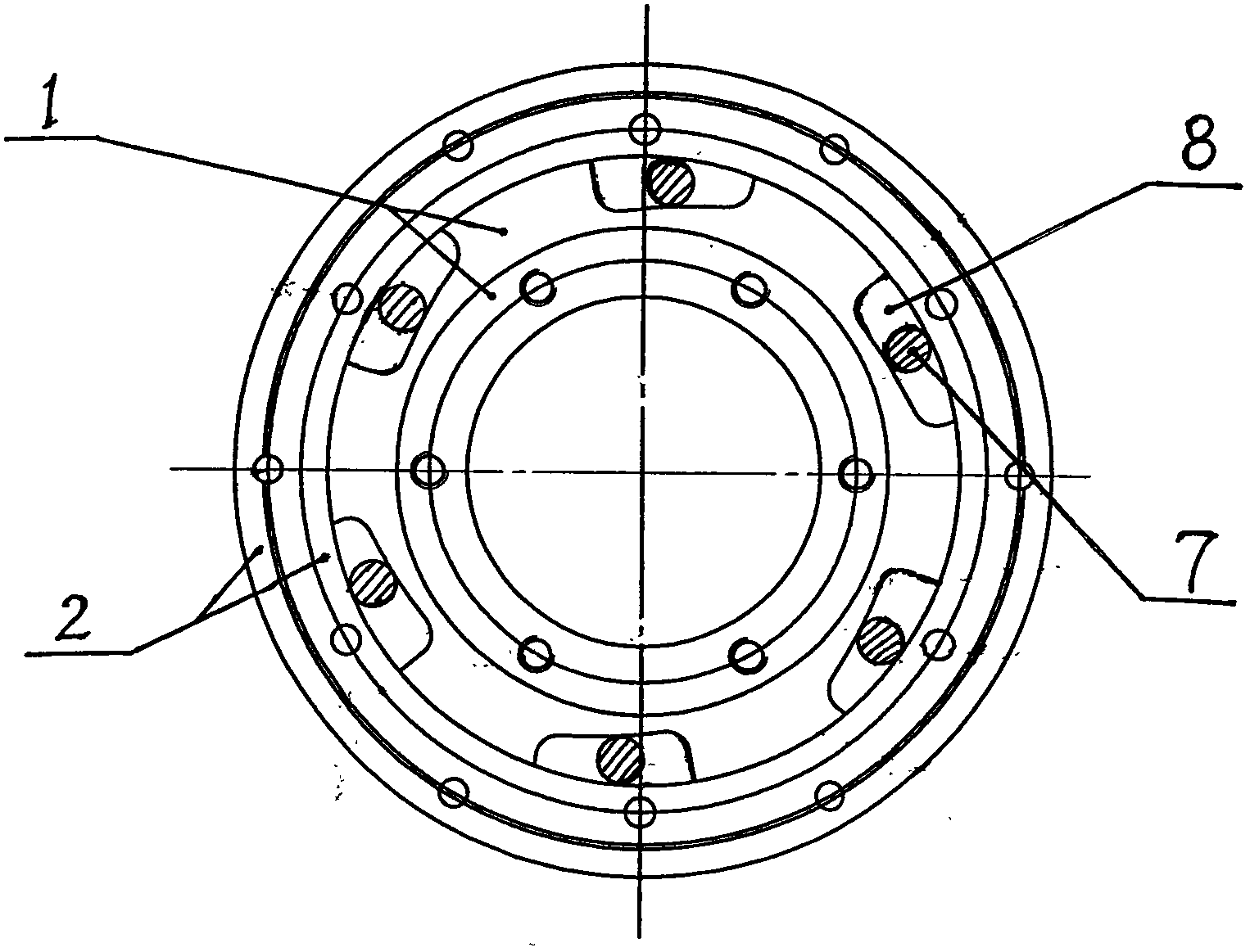
[0024] In Embodiment 2, the present invention has the same structure as that in Embodiment 1 except that the above-mentioned compression spring is omitted and the transmission part is a cylinder. exist image 3 In the schematic diagram shown in the structure, the present invention includes an inner shaft sleeve 1, an outer ring 2 arranged on its periphery, and 6 transmission parts that transmit the rotational force of the inner shaft sleeve 1 to the outer ring 2, and the inner shaft sleeve The outer edge of 1 is evenly provided with 6 wedge-shaped grooves, wedge-shaped groove 8 is one of them, and the above-mentioned 6 transmission parts are cylinders that can be arranged in the wedge-shaped grooves, and cylinder 7 is In one of them, the cylinder 7 is arranged in the wedge-shaped groove 8 , and its axis line is in the same direction as the axis line of the inner sleeve 1 , and the arrangement of each cylinder is the same as that of the cylinder 7 .

Embodiment 3

[0025] Embodiment 3, except that only one wedge-shaped groove and the corresponding ball are provided, other structures of the present invention are the same as those described in Embodiment 1. exist Figure 4 In the structural schematic diagram shown, the present invention includes an inner shaft sleeve 1, an outer ring 2 arranged on its periphery, and a transmission component that transmits the rotational force of the inner shaft sleeve 1 to the outer ring 2, that is, a round ball 3. A wedge-shaped groove is evenly arranged on the outer edge of the bushing 1, that is, a wedge-shaped groove 5. One end of the compression spring 4 is set on the inner wall of the deepest end of the wedge-shaped groove 5, and the other end is set on the ball 3 On, it forms a compressible top tight fit structure with the round ball 3 .


PUM


Abstract

The invention relates to a high-reliability clutch mechanism which comprises an inner shaft sleeve 1, an outer sleeve ring 2 and a driving component, wherein the outer edge of the inner shaft sleeve 1 is at least provided with a wedge-shaped groove; the driving component is arranged in the wedge-shaped groove, and the driving part, the outer sleeve ring 2 and the wedge-shaped groove form a one-way close fit structure capable of realizing forward-rotation clamping. The high-reliability clutch mechanism can be used for solving the problems of high fault occurrence possibility, poor reliability and high abrasion possibility of an existing clutch mechanism, has the advantages of high operation reliability, high stability, low noise, simple structure, easiness for manufacturing, high durability and the like, and is mainly used for manufacturing clutch devices of various vehicles and power devices.

Description

technical field [0001] The invention relates to a clutch control device used in a mechanical transmission system, in particular to a high-reliability clutch mechanism. Background technique [0002] At present, the clutch control device used for power transmission on bicycles, electric bicycles, and electric tricycles is a ratchet mechanism, which is mainly composed of a ratchet wheel with a tooth groove and a pawl linked with the drive shaft, which drives the pawl to rotate through the drive shaft , the ratchets are pushed into the tooth grooves on the ratchet in turn along with the rotation, pushing the ratchet to rotate, thereby driving the wheel to rotate. Because the pawl and each tooth groove on the ratchet wheel are always single-point line contact push-up cooperation, and the pawl slides to the next adjacent tooth groove after pushing a tooth groove on the ratchet wheel, the ratchet is always in the same position. Stop sliding and push the top, because the pawl is pu...

Claims


Application Information

Patent Timeline
Patent Type & Authority Applications(China)
IPC IPC(8): F16D41/06F16D41/064
Inventor 马骥马健
Owner 马骥
Why Eureka
Try Eureka