Cone beam CT scatter correction method and system

A scatter correction, cone beam technology, applied in image data processing, instruments, calculations, etc., to reduce the effect of scattering, overcome poor imaging quality, and enhance image quality

Inactive Publication Date: 2014-02-12
JIANGSU CHAOWEI TECH DEV
View PDF5 Cites 21 Cited by
  • Summary
  • Abstract
  • Description
  • Claims
  • Application Information

AI Technical Summary

Problems solved by technology

Therefore, in cone-beam CT, scatter is the main cause of reconstructed image degradation
Artifacts caused by scattering and inaccurate CT numbers seriously affect the analysis and judgment of reconstructed images

Method used


Image

  • Cone beam CT scatter correction method and system
  • Cone beam CT scatter correction method and system
  • Cone beam CT scatter correction method and system

Examples


Embodiment

[0039] The technical scheme of the invention is a cone beam CT scattering correction method based on an attenuating screen.

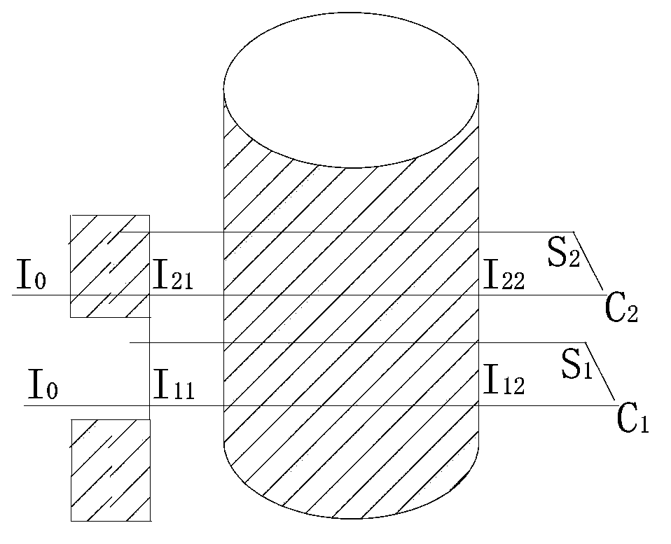
[0040] Cone beam CT scattering correction based on the attenuating screen is to add a mesh attenuating plate between the ray source and the irradiated object to perform different attenuation on the rays at adjacent positions, and use the K-N formula to derive the scattering distribution. Finally, the scatter distribution image is subtracted from the acquired image to obtain the corrected image.

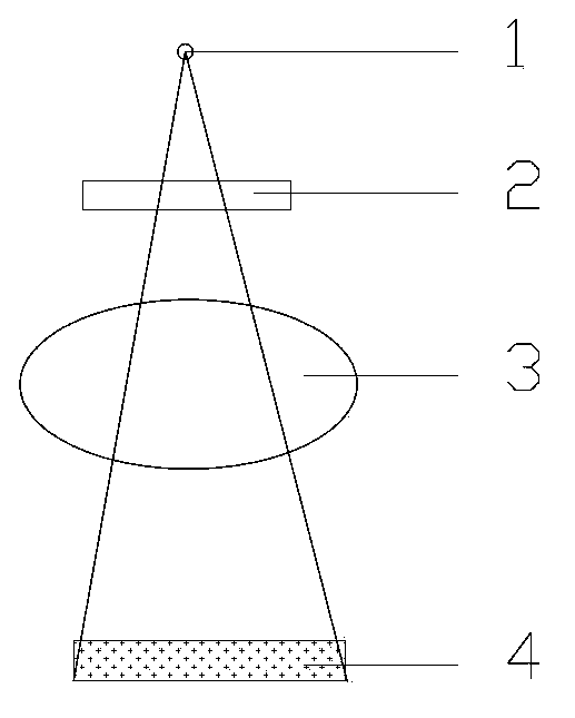
[0041] system structure in figure 1 Given in , the system consists of a ray source 1, an attenuation screen 2, a phantom 3, and a flat panel detector 4. The present invention is characterized in that an attenuation screen 2 is added between the radiation source 1 and the phantom 3 .

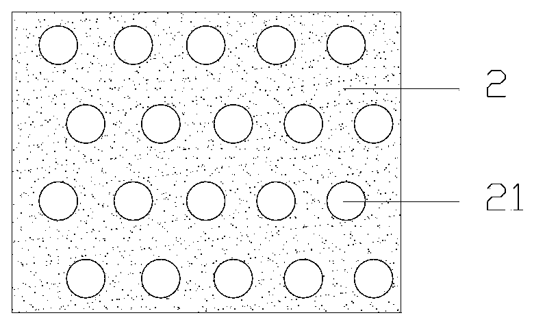
[0042] The attenuation screen 2 is made of an aluminum plate with a size (12CM*12CM) and a thickness of 2mm, and 900 small holes 21 are evenly distributed on it, and the structu...


PUM


Abstract

The invention relates to a cone beam CT scatter correction method and system. The method comprises the following steps that an attenuation coefficient matrix of an X-ray passing through an attenuation screen on a detector is calculated; under the condition that the attenuation screen is included, projected images of a radiated object are acquired; scatter correction is conducted on each projected image; the projected image of a template body without the attenuation screen is estimated through the attenuation coefficient matrix; the image is reconstructed through a FDK algorithm. The cone beam CT scatter correction method can effectively lower the scatter influence on cone beam CT image reconstruction, and the image quality is improved. Circular scanning is only conducted on cone beam CT for one time, and irradiation dose is not additionally increased. The cone beam CT scatter correction method is simple to implement, and the main structure and the stability of the cone beam CT are not changed. The cone beam CT scatter correction system can effectively lower the scatter influence on cone beam CT image reconstruction, improve the image quality, and overcome the technical difficulty of poor cone beam CT imaging quality.

Description

technical field [0001] The invention relates to a cone-beam CT scattering correction method and system. Background technique [0002] Compared with the traditional two-dimensional CT, the cone beam CT based on the flat panel detector has outstanding advantages, mainly in the fact that the projection of hundreds or even thousands of tomographic images can be obtained within one circular scanning cycle of the cone beam CT, which has more advantages. High scanning speed and radiation utilization, and effectively reduce the load output of X-ray tubes, reducing scanning costs. In addition, cone-beam CT can obtain higher-precision spatial resolution, and can obtain three-dimensional tomographic image data comparable to the spatial resolution of film projection imaging, while the contrast is 50 to 100 times higher than that. Although cone-beam CT has obvious advantages, because cone-beam CT uses a large-scale X-ray flat panel detector, the image quality is more susceptible to X-ra...

Claims


Application Information

Patent Timeline
Patent Type & Authority Applications(China)
IPC IPC(8): G06T5/00A61B6/03
Inventor 谢世朋石汉青赵守仁陈方伦曹磊
Owner JIANGSU CHAOWEI TECH DEV
Why Eureka
Try Eureka