LED display device

A LED display screen and display device technology, applied in the field of display screens, can solve problems such as low resolution, poor optical uniformity of display images, and inability to combine LED pixels well, so as to achieve good optical uniformity, ensure image quality and display The effect of sharpness

Inactive Publication Date: 2014-02-12
GUANGDONG VTRON TECH CO LTD
View PDF12 Cites 19 Cited by
  • Summary
  • Abstract
  • Description
  • Claims
  • Application Information

AI Technical Summary

Problems solved by technology

[0007] For example, one solution is to fix an optical curtain in front of the display unit board, cover the optical curtain with a coating of diffusing particles, and use the coating of diffusing particles to achieve light amplification and diffusion, but this method only relies on scattering particles to achieve light amplification and diffusion , in order to eliminate the Moiré fringe potential, the scattering particles must strengthen the scattering degree, which causes a large loss of light energy and has a great impact on the imaging quality, resulting in low resolution and poor visual perception. Streaks also cause a reduction in image quality
[0008] Another solution is to set an optical lens film on the surface of the display screen, and use the evenly covered bead lens on the optical lens film to enlarge and display the LED pixels. However, the size of the bead lens is small. Due to the process, the distribution is uniform but It is also relatively random, and cannot be well combined with LED pixels, which directly causes poor image quality
[0009] Another solution is to directly set a convex lens on the display substrate, and use the convex lens to enlarge a single pixel. This solution is to use a convex lens to enlarge a pixel. The aberration of the formed image is large, and the optical uniformity of the display screen is also low. poor

Method used


Image

  • LED display device
  • LED display device
  • LED display device

Examples


Embodiment 1

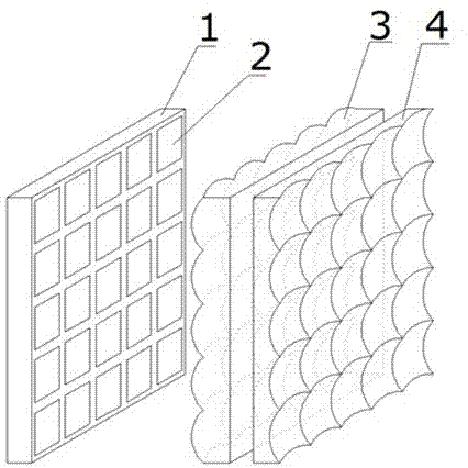
[0033] Such as figure 2 As shown, it is a schematic structural diagram of a specific embodiment of an LED display device according to the present invention. see figure 2 An LED display device in this specific embodiment includes an LED display screen 1, a lens array I3 and a lens array II4 are sequentially arranged in front of the LED display screen 1, and the LED pixels 2 on the LED display screen 1 pass through the lens array I3 and the lens array II4. Afterwards, it becomes an upright enlarged image. In this specific embodiment, the lens array I3 is arranged between the LED display screen 1 and the lens array II4, and the joint action of the lens array I3 and the lens array II4 forms an upright enlarged image for the LED pixels 2 of the LED display screen 1 . Because the LED pixel 2 is enlarged, the non-luminous gap between the pixels is eliminated, thereby eliminating the occurrence of inclination angles between the CCD or CMOS sensor pixels and the LED pixels when the...

Embodiment 2

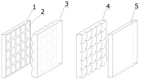
[0055] Such as figure 2 As shown, an LED display device of this embodiment includes an LED display screen 1, and a lens array I3 and a lens array II4 are sequentially arranged in front of the LED display screen 1, and the lenses in the lens array I3 and the lens array II4 form a regular two-dimensional network. shape distribution, and lens array I3 and lens array II4 are convex lenses. The lens array I3 is placed so that the LED pixel 2 is located near twice the focal length of the lens array I3, and the LED pixel 2 forms an inverted transitional image of equal size through the lens array I3. This transitional image is used as the object of the lens array II4, and the object distance is within Between one focal length and two focal lengths of the array II 4 , an upright enlarged real image can be finally formed for the LED pixel 2 . Since the finally formed image is a real image, a real image receiving screen 5 can be arranged at the final imaging surface of the two lens arr...

Embodiment 3

[0060] Such as image 3 As shown, an LED display device of this embodiment includes an LED display screen 1, and a lens array I3 and a lens array II4 are sequentially arranged in front of the LED display screen 1, and the lenses in the lens array I3 and the lens array II4 form a regular two-dimensional network. Shape distribution, the lenses in lens array I3 are convex lenses, and the lenses in lens array II4 are concave lenses. The lens array I3 is placed so that the LED pixel 2 is located near twice the focal length of the lens array I3, and the LED pixel 2 forms an inverted transitional image of equal size through the lens array I3. This transitional image is used as the object of the lens array II4, and the object distance is within Between one focal length and two focal lengths of the array II 4 , an upright enlarged image can finally be formed for the LED pixel 2 . The convex-concave lens combination can eliminate more aberrations, so that the imaging quality of the LED...


PUM


Abstract

The invention relates to the field of display screens, in particular to an LED display device. The LED display device comprises an LED display screen, a lens array I and a lens array II are sequentially arranged in the front of the LED display screen, and an LED pixel on the LED display screen transmits through the lens array I and the lens array II to form a vertical enlarged image. According to the LED display device, the surface of the LED display screen is covered with the lens array I and the lens array II, the LED pixel is enlarged by the joint effect of the lens array I and the lens array II, and non-luminance gaps between pixels are removed, so that the moire fringe phenomenon between a CCD or CMOS sensor pixel and the LED pixel caused by an included angle when the LED screen is shot by a camera or other digital products is removed, and meanwhile visual image quality and display definition are ensured.

Description

technical field [0001] The present invention relates to the field of display screens, and more specifically, to an LED display device. Background technique [0002] LED (Light Emitting Diode) is a light-emitting diode. Its core part is the PN junction of semiconductor materials. Under the action of forward voltage, electrons are injected from the N region into the P region, and holes are injected from the P region into the N region. Carriers and majority carriers recombine to emit light. [0003] In recent years, with the continuous development of LED packaging and epitaxial wafer technology, coupled with its advantages of energy saving and environmental protection, long service life, high brightness, rich colors, etc., LED large-screen display walls have been widely used, whether in outdoor busy streets Large LED screen display walls can be seen everywhere in squares, indoor performing arts centers or exhibition venues, live news studios and variety show recording sites. ...

Claims


Application Information

Patent Timeline
Patent Type & Authority Applications(China)
IPC IPC(8): G09F9/33G02B3/00
Inventor 王新星罗振华梁明浩陈庆伟
Owner GUANGDONG VTRON TECH CO LTD
Why Eureka
Try Eureka