
Charge recovery in power converter driver stages

A technology of power converter and drive circuit, which is applied in the direction of output power conversion device, conversion of DC power input to DC power output, and high-efficiency power electronic conversion, which can solve the problem of increasing the size and cost of the drive circuit, increasing the complexity of the drive, and reducing And other issues

Active Publication Date: 2014-02-12
INFINEON TECH AUSTRIA AG
View PDF5 Cites 8 Cited by
  • Summary
  • Abstract
  • Description
  • Claims
  • Application Information

AI Technical Summary

Problems solved by technology

Typically, the energy used for the gate drive process is then dissipated
Some conventional approaches try to recover a portion of the gate drive energy by storing energy in an external capacitor, which adds complexity to the driver as additional pins and external components are required
The storage capacitor could instead be integrated in the driver, but doing so increases the size and cost of the driver circuit

Method used


Image

  • Charge recovery in power converter driver stages
  • Charge recovery in power converter driver stages
  • Charge recovery in power converter driver stages

Examples


Embodiment Construction

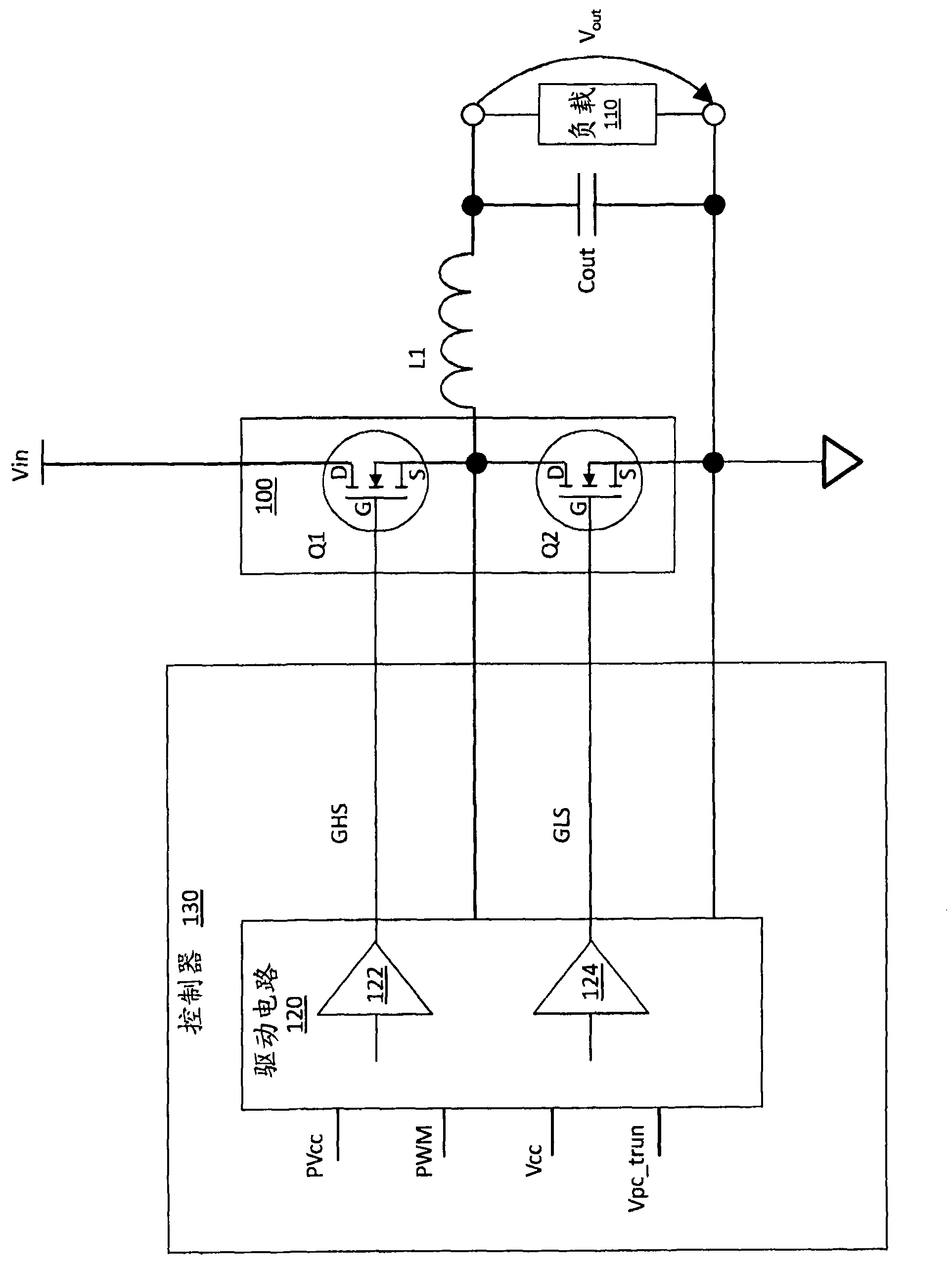
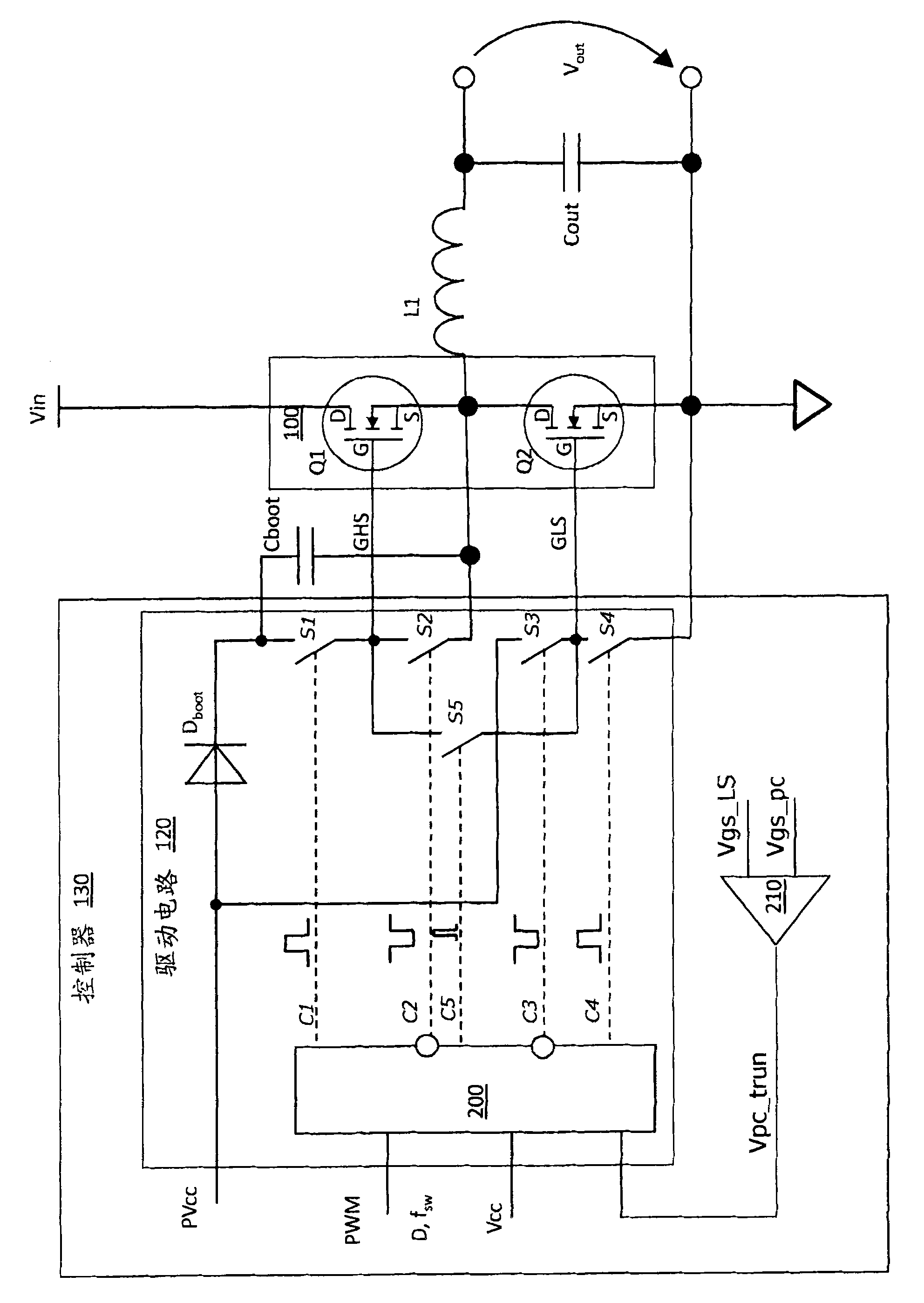
[0016] Embodiments described herein provide charge recovery in the power converter driver stage by using the gate charge of the high-side transistor of the power stage to precharge the low-side transistor of the power stage directly. The direct charge recovery technique described in this article can be applied to several switching regulator architectures, including: buck; boost-buck; push-pull; half-bridge; full-bridge. A buck converter reduces the DC voltage to a lower DC voltage. A buck-boost converter generates an output voltage that is opposite in polarity to the input. Push-pull converters are two-transistor converters that are especially efficient at low input voltages. Half-bridge converters are two-transistor converters used in many off-line applications. A full-bridge converter is a four-transistor converter typically used in off-line designs that can generate very high output power.

[0017] For each type of switching regulator architecture, efficient operation is...


PUM


Abstract

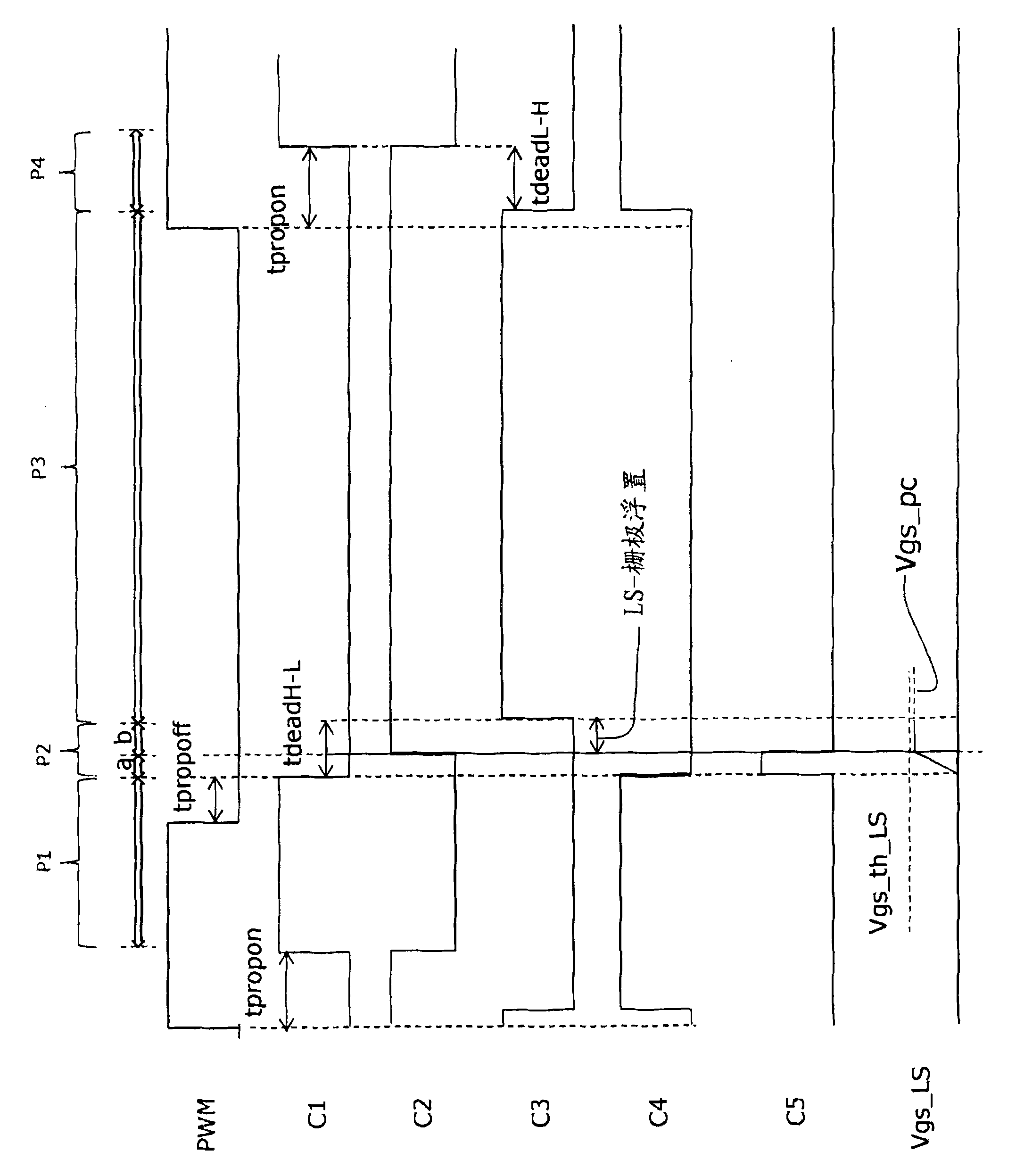
A power converter includes a first transistor operable to source current to a load when switched on, a second transistor operable to freewheel inductor current or sink current from the load when switched on, and a driver circuit. The driver circuit is operable to switch the first transistor on and the second transistor off during a first period, switch the first transistor off and the second transistor on during a third period after the first period, and connect a gate of the first transistor to a gate of the second transistor during a second period between the first and third periods when the gates of both transistors are floating.

Description

technical field [0001] The present application relates to power converter driver stages, particularly charge recovery in power converter driver stages. Background technique [0002] Switching power converters are widely used in high power applications due to their high efficiency and small size. Converter efficiency is increasingly important at low and medium power levels. For example, buck converters are particularly well suited to supply high current at the low voltages required by state of the art high performance integrated circuits such as microprocessors, graphics processors and network processors. Typically, active components such as pulse width modulation controllers (PWM), drivers, power MOSFETs (metal oxide semiconductor field effect transistors) and passive components such as inductors, transformers or coupled inductors, capacitors and resistor) to implement a buck converter. [0003] Most traditional buck converters use direct drive to turn on the MOSFETs of t...

Claims


Application Information

Patent Timeline
IPC IPC(8): H02M3/155
CPCG05F3/02H02M1/08H02M3/1588Y02B70/10
Inventor J·A·埃朱里
Owner INFINEON TECH AUSTRIA AG
Learn More