DMRS processing method and device
A processing method and high-level configuration technology, applied in the field of communication, can solve problems such as the absence of technical support
- Summary
- Abstract
- Description
- Claims
- Application Information
AI Technical Summary
Problems solved by technology
Method used
Image
Examples
Embodiment 1
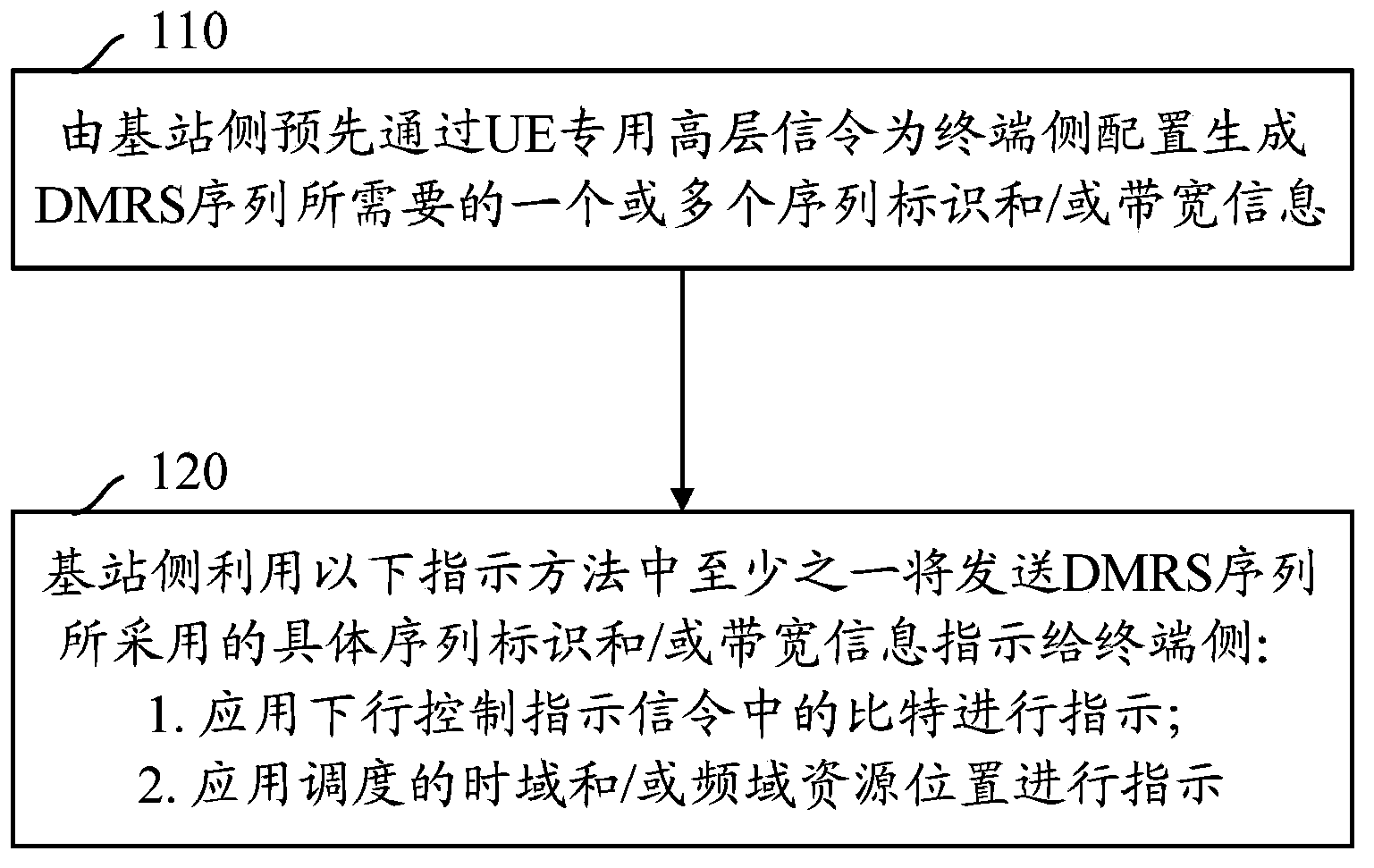
[0158] Assuming that the version of UE1 is R11 or higher, the base station configures UE1 with two sequence identifiers (X0, X1) through UE-Specific (UE-specific) high-level signaling. When the base station uses DMRS-related transmission modes in the PDSCH area When data is sent to the terminal side in the CRS subframe and format 1A is used for DCI configuration, the centralized / distributed VRB mapping in DCI Format 1A assigns a 1-bit identifier to indicate the two high-level configurations used by the DMRS sequence sent by the base station side. A sequence ID and / or a specific sequence ID and / or bandwidth information in the two bandwidth information. For example, when the value of the 1 bit is 0, it indicates that the DMRS sequence is generated by X0; when the value of the 1 bit is 1, it indicates that the DMRS sequence is generated by X1.
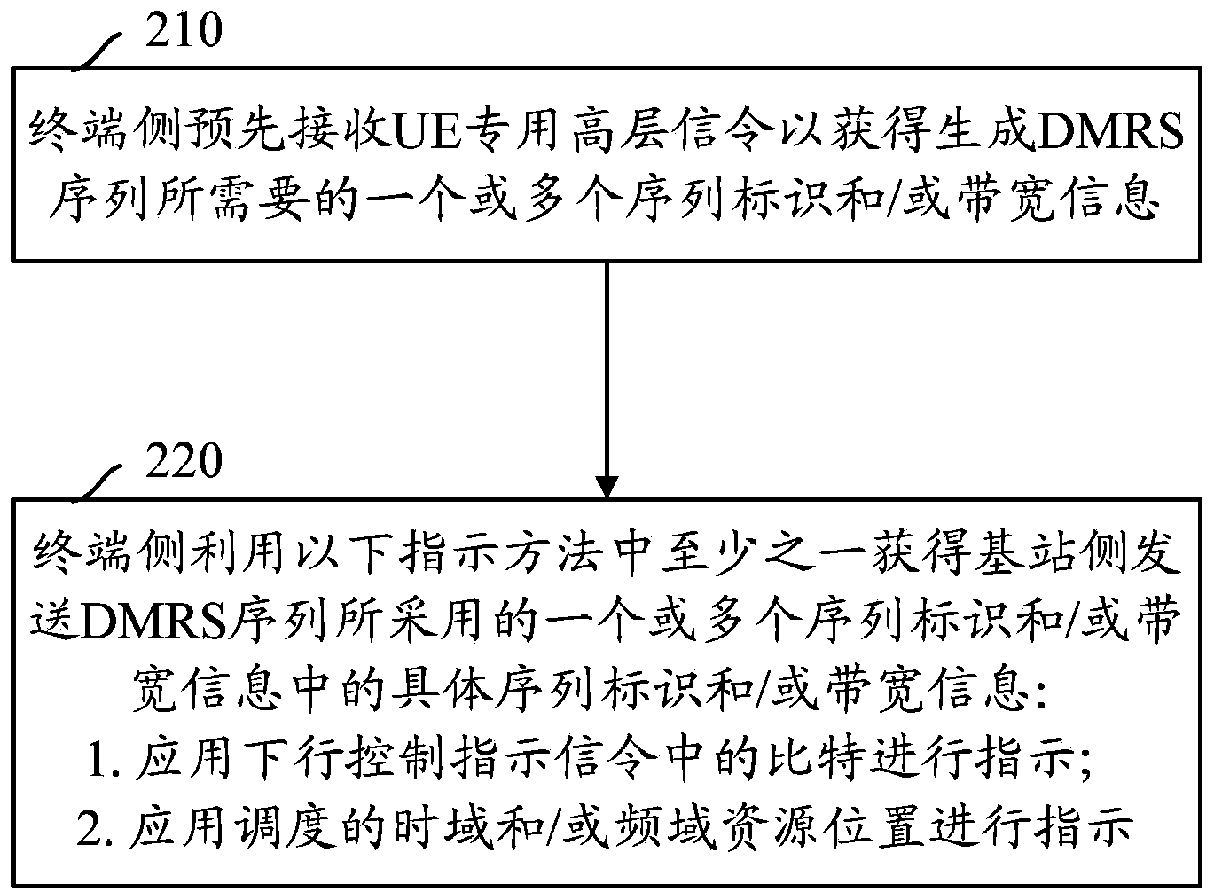
[0159] UE1 obtains the two sequence identifiers and / or the two bandwidth information of the high-level configuration adopted by the DMRS...
Embodiment 2
[0161] Assuming that the version of UE1 is R11 or higher, the base station configures two bandwidth information (S0, S1) for UE1 through UE-Specific (UE-specific) high-level signaling. When the base station uses DMRS-related transmission modes in the PDSCH area When data is sent to the terminal side in the CRS subframe and format 1A is used for DCI configuration, the centralized / distributed VRB mapping in DCI Format 1A assigns a 1-bit identifier to indicate the high-level configuration used by the base station side to send the DMRS sequence. Specific bandwidth information in each bandwidth information. For example, when the value of the 1 bit is 0, it indicates that the DMRS sequence is generated by using S0; when the value of the 1 bit is 1, it indicates that the DMRS sequence is generated by using S1.
[0162] UE1 obtains the specific bandwidth information among the two bandwidth information configured by the high layer used by the base station to send the DMRS sequence by b...
Embodiment 3
[0164] Assuming that the version of UE1 is R11 or higher, the base station configures UE1 with two bandwidth information (S0, S1) and two sequence identifiers (X0, X1) through UE-Specific (UE-specific) high-layer signaling. When the base station uses When the DMRS-related transmission mode sends data to the terminal side in a subframe in which there is no CRS in the PDSCH region and uses format 1A for DCI configuration, the centralized / distributed VRB mapping in DCI Format 1A assigns a 1-bit identifier to indicate the base station side The specific sequence identifier and bandwidth information in the two bandwidth information and the two sequence identifiers configured by the high layer used to send the DMRS sequence. For example, when the value of the 1 bit is 0, it indicates that the DMRS sequence is generated by using S0 and X0; when the value of the 1 bit is 1, it indicates that the DMRS sequence is generated by using S1 and X1.
[0165] UE1 obtains the two bandwidth infor...
PUM
 Abstract
Description
Claims
Application Information
 - R&D
- Intellectual Property
- Life Sciences
- Materials
- Tech Scout
- Unparalleled Data Quality
- Higher Quality Content
- 60% Fewer Hallucinations
Browse by: Latest US Patents, China's latest patents, Technical Efficacy Thesaurus, Application Domain, Technology Topic, Popular Technical Reports.
© 2025 PatSnap. All rights reserved.Legal|Privacy policy|Modern Slavery Act Transparency Statement|Sitemap|About US| Contact US: help@patsnap.com


