
Variable polarity arc welding power supply and control method thereof

An arc welding power supply and polarity-changing technology, which is applied in arc welding equipment, manufacturing tools, welding equipment, etc., can solve the problem of unstable welding arc, variable polarity positive and negative half-waves are not easy to control in consistency, and does not consider the direction of the electrode to the mother. The discharge capacity of the material is different, so as to achieve the effect of precise control

Active Publication Date: 2014-02-19
PANASONIC WELDING SYST TANGSHAN
View PDF0 Cites 2 Cited by
  • Summary
  • Abstract
  • Description
  • Claims
  • Application Information

AI Technical Summary

Problems solved by technology

Due to the large difference between the discharge ability of the variable polarity arc welding electrode to the base metal and the discharge capacity of the base metal to the electrode, it is difficult to achieve consistent control of the positive and negative half waves of the variable polarity arc welding during polarity variable welding, so that it cannot be realized The stable arc performance of variable polarity welding can easily lead to serious welding burnout, unstable welding arc, poor weld formation, and spatter in welding
[0003] At present, the variable polarity arc welding power supply is controlled by fixed control parameters, and the difference between the discharge capacity of the electrode to the base metal and the discharge capacity of the base metal to the electrode is not considered in the control. Therefore, the above-mentioned shortcomings are common.

Method used


Image

  • Variable polarity arc welding power supply and control method thereof
  • Variable polarity arc welding power supply and control method thereof
  • Variable polarity arc welding power supply and control method thereof

Examples


no. 1 example

[0022] [Hardware structure]

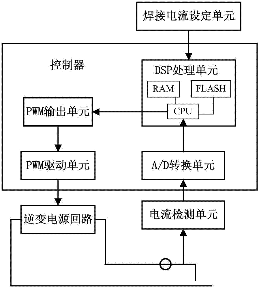
[0023] Refer below figure 1 The hardware structure of the polarity-changing arc welding control device according to the first embodiment of the present invention will be described.

[0024] The polarity-changing arc welding power source shown in this embodiment is a TIG welding power source.

[0025] Such as figure 1 As shown, the variable polarity arc welding power source of the present invention includes: a welding current setting unit, a current detection unit, a controller and an inverter power circuit. The welding current setting unit, the current detecting unit and the inverter power circuit are respectively electrically connected to the controller. The welding current setting unit is used to set an ideal welding current. The current detection unit is used to detect the welding current, which can adopt a current transformer. The inverter power circuit is used to output welding current. The controller is used to control the inverter pow...


PUM


Abstract

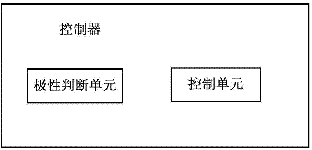
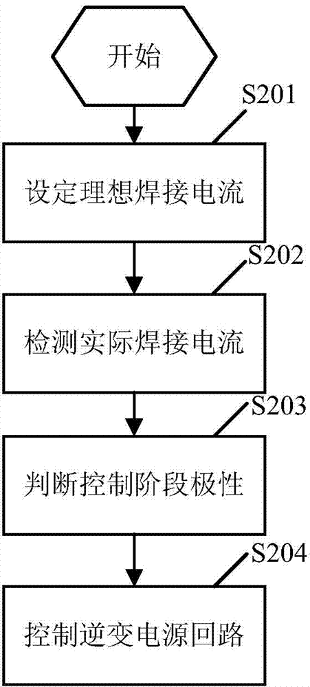
The invention provides a variable polarity arc welding power supply and a control method thereof and belongs to the technical field of welding. The variable polarity arc welding power supply comprises a welding current setting unit, a current detection unit, a controller and an inverter power supply circuit. The welding current setting unit, the current detection unit and the inverter power supply circuit are respectively electrically connected with the controller, the welding current setting unit is used for setting an ideal welding current, and the current detection unit is used for detecting an actual welding current. The controller comprises a polarity judging unit and a control unit, the polarity judging unit is used for judging polarity control phases according to the actual welding current detected through the current detection unit, the control unit is used for controlling the inverter power supply circuit to output the welding current according to the judged polarity, the set ideal welding current and the detected actual welding current. Therefore, the variable polarity arc welding power supply can be controlled by different control parameters in the different polarity control phases, the problem that bipolarity waveforms cannot be fully realized when the parameters are fixed is effectively solved, and accurate control of variable polarity arc welding is realized.

Description

[technical field] [0001] The invention relates to the field of welding technology, in particular to a variable polarity arc welding power source and a control method thereof. [Background technique] [0002] Variable polarity arc welding is widely used in the welding process of aluminum and aluminum alloys. Variable polarity arc welding includes AC tungsten argon arc welding (TIG) and so on. For the variable polarity arc welding power supply, when the positive half-wave control is applied to the electrode, the positive voltage is applied to the electrode, the base metal is negative, and the current flows from the electrode to the base metal; when the negative half-wave control is applied, the positive voltage is applied to the base metal, the electrode is negative, and the current Flow from the base metal to the electrode. Due to the large difference between the discharge ability of the variable polarity arc welding electrode to the base metal and the discharge capacity of ...

Claims


Application Information

Patent Timeline
Patent Type & Authority Applications(China)
IPC IPC(8): B23K9/10B23K9/095
CPCB23K9/095B23K9/1056
Inventor 王帅韩勇李文举赵素梅李松惠昭
Owner PANASONIC WELDING SYST TANGSHAN
Learn More