
Optical fiber terminating device

An end-to-end and optical fiber technology, which is applied in the direction of grinding devices, grinding machine tools, working carriers, etc., can solve the problems of affecting the processing accuracy of the workpiece to be polished, the increase of the cost of the grinding process, and the scratches of the workpiece to be polished.

Active Publication Date: 2014-02-19
HENAN HUACHUANG COMM EQUIP
View PDF8 Cites 8 Cited by
  • Summary
  • Abstract
  • Description
  • Claims
  • Application Information

AI Technical Summary

Problems solved by technology

[0003] The Chinese patent application number 200320124910.8 discloses a multi-disk multi-grain gemstone grinding and polishing device. The turntable assembled in the indexing disc and the fixture assembled on the turntable, the fixtures and the grinding discs are respectively arranged correspondingly, and the grinding motors connected with the corresponding belt transmissions of each grinding disc and the rotating shaft of the turntable are fixed on the frame The indexing motor connected by belt transmission, when in use, each grinding disc rotates by itself under the drive of the grinding motor to grind the workpiece, and the turntable drives the fixture to revolve under the drive of the indexing motor, so that the workpiece clamped on each fixture Grinding by grinding discs with different grinding precision forms a circular flow automatic circulation operation, but during the grinding process, the chips generated between the workpiece and the grinding disc will affect the processing accuracy of the workpiece to be ground, making the workpiece to be ground was scratched; and after using the existing grinding fluid filling device, the timing and position of each filling of grinding fluid needs to be controlled by the controller and the operator, which makes the operation of the grinding fluid filling process difficult, so that the entire Increased costs for the grinding process

Method used


Image

  • Optical fiber terminating device
  • Optical fiber terminating device
  • Optical fiber terminating device

Examples


Embodiment Construction

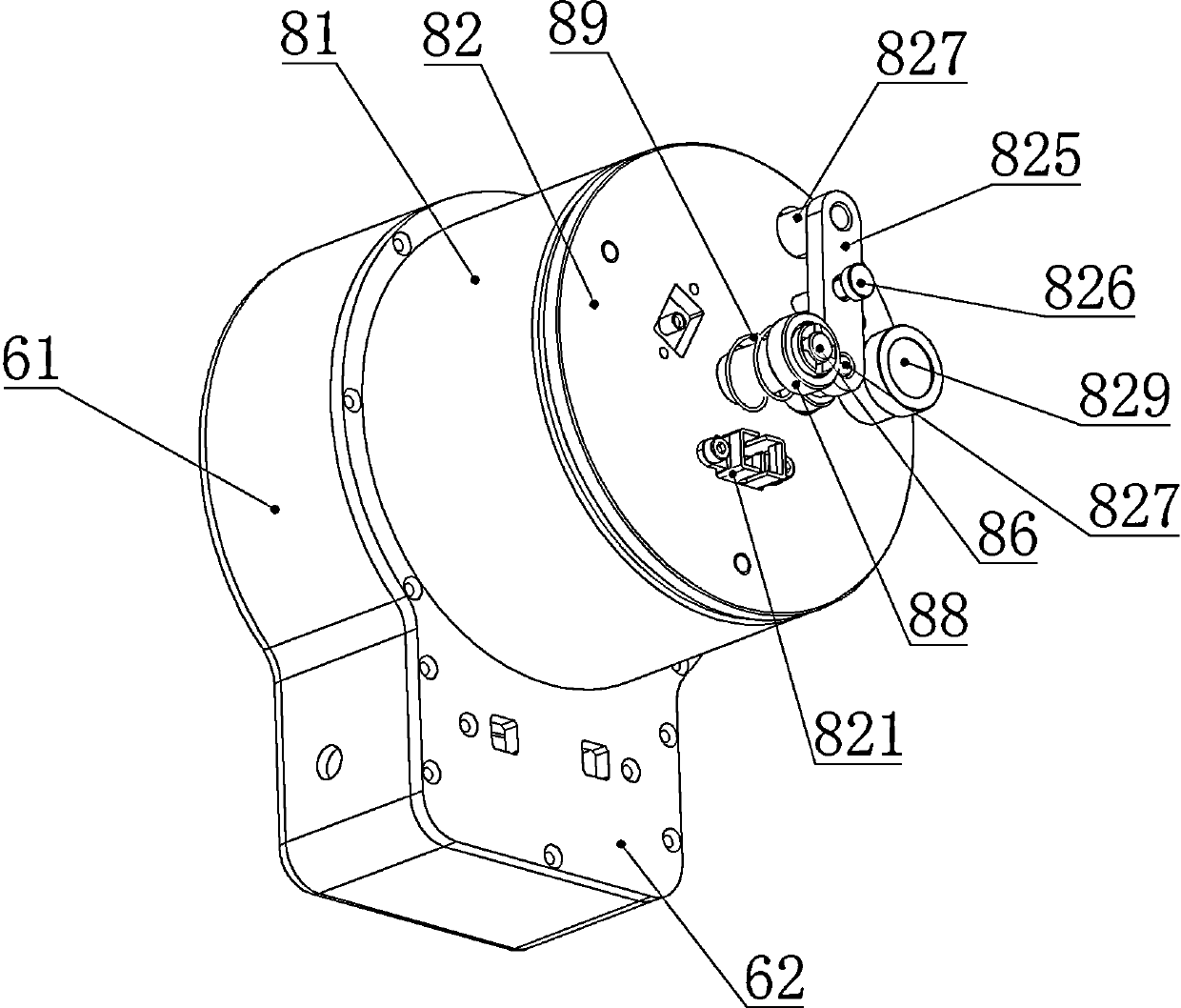
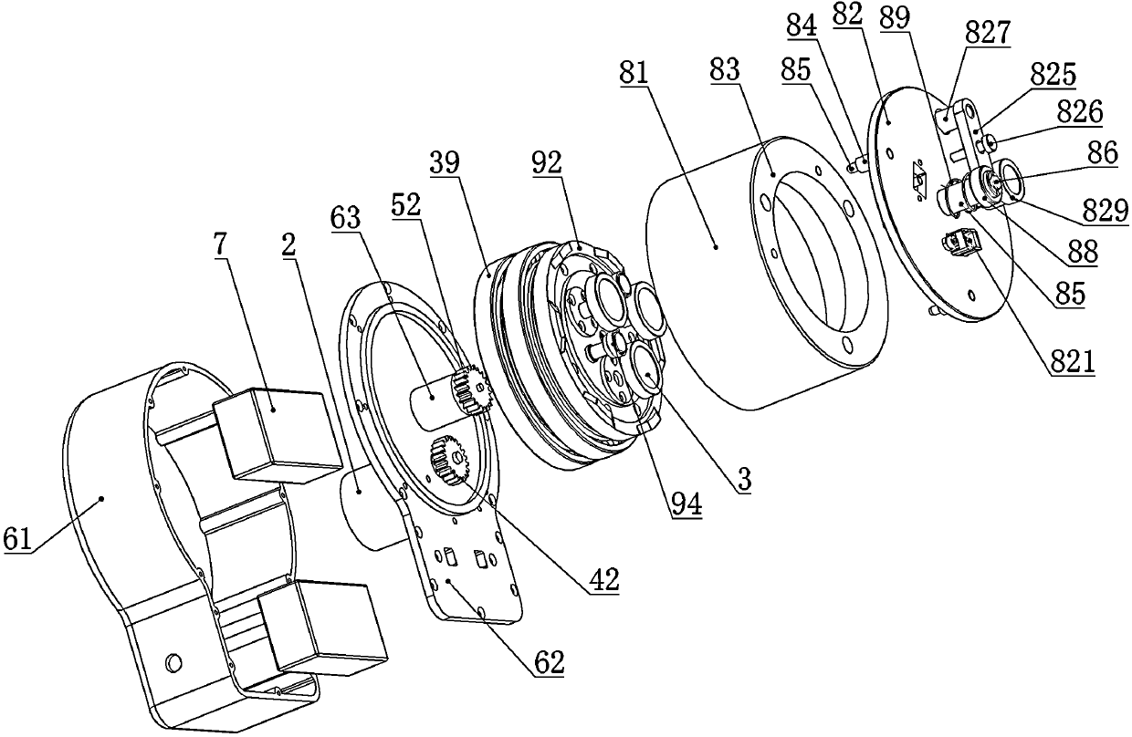
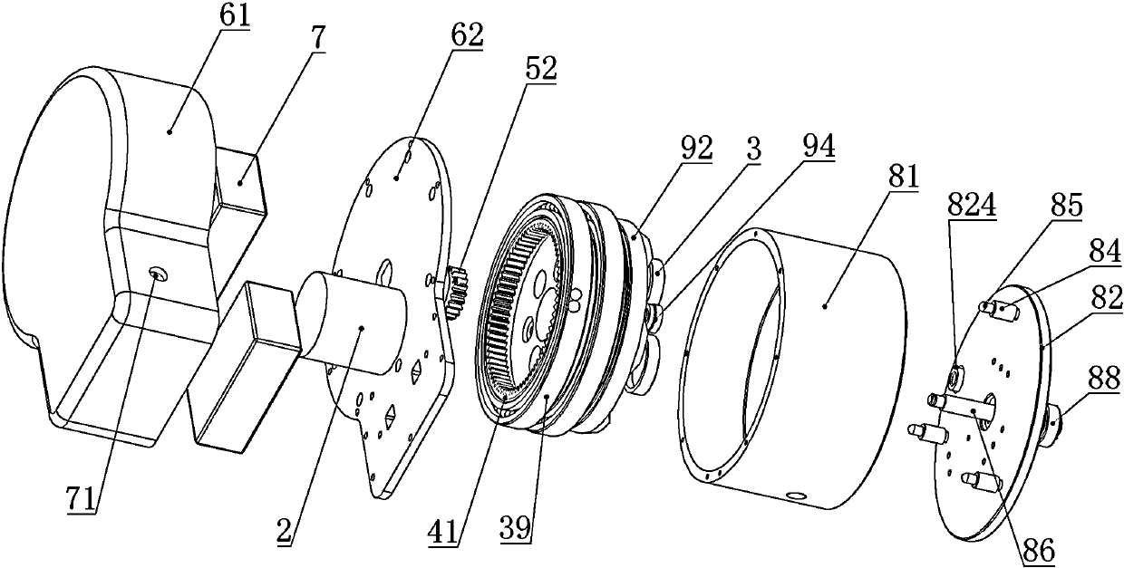
[0035] Embodiments of the optical fiber terminator of the present invention: as Figure 1 to Figure 18 As shown, the optical fiber terminator is an optical fiber terminator for grinding the end face of an optical fiber ferrule. The optical fiber terminator includes a machine base, a grinding motor 1, an indexing tray, an indexing motor 2, a grinding disc 3 and The machine cover, wherein the indexing tray is rotated and assembled in the machine cover through the indexing bearing 39, and there are three grinding discs 3, and the upper disc surfaces of the three grinding discs 3 are respectively provided with rough grinding heads, fine grinding heads and grinding heads with different grinding accuracy. Polishing grinding head, the lower end of the grinding disc 3 is fixed with a rotating shaft 31 mounted on the indexing tray, so that the three grinding discs 3 can revolve with the indexing tray, and a revolution passive ring gear is fixed at the bottom of the indexing tray 41, th...


PUM


Abstract

The invention discloses an optical fiber terminating device. According to the optical fiber terminating device, a clamp disk is vertically guided and assembled on a displacement tray, a fluid complementing hole is formed in the clamp disk above a displacement path, a fluid storage cavity is formed in a large-hole section of the fluid complementing hole, a pressing head which is assembled on the clamp disk in a limited mode is arranged at the upper portion of the fluid storage cavity, a driving pushing body and a driven pushing body are arranged between the clamp disk and the displacement tray, and the driving pushing body and the driven pushing body are in interval pushing fit to form an interval pushing mechanism. When a grinding disk and the fluid complementing hole are vertically opposite to each other, the driving pushing body and the driven pushing body are pushed to be matched, the clamp disk and the pressing head can move oppositely, the fluid storage cavity is compressed, grinding fluid stored in a cavity or sponge in the fluid storage cavity is complemented into a small-hole section of the fluid complementing hole by the pressing head, and then the grinding fluid is injected into the grinding disk through the small-hole section of the fluid complementing hole. Thus, the difficulty in choosing injection time and the injection positions is reduced, and the injection accuracy and the injection reliability are improved.

Description

technical field [0001] The invention relates to an optical fiber terminator. Background technique [0002] At present, with the popularization of high-bandwidth multimedia applications such as video and digital TV, large commercial customers have high requirements for network bandwidth and stability. Domestic discussions on FTTH projects (fiber-to-the-home projects) are gradually heating up. Driven by market demand, FTTH project has become a new bright spot in the development of my country's telecommunications industry in the next few years. In FTTH projects, hot-melt technology, pre-embedded cold connection technology, and non-embedded cold connection technology are usually used for on-site assembly of optical fiber active connectors. Low efficiency and other characteristics are widely used, so the on-site grinding technology of the ferrule in the optical fiber active connector has become a key process for the on-site assembly of the optical fiber active connector. The grin...

Claims


Application Information

Patent Timeline
IPC IPC(8): B24B37/10
CPCB24B37/10B24B37/30B24B37/34
Inventor 邵广海
Owner HENAN HUACHUANG COMM EQUIP
Learn More