
Accumulator disc type electric locomotive

A technology for batteries and electric locomotives, applied in electric locomotives, locomotives, motor vehicles, etc., can solve the problems of poor safety performance, long braking distance, easy to produce shock, etc., and achieve fast response, smooth speed regulation, and excellent braking performance. Effect

Active Publication Date: 2014-02-19
安徽中车瑞达电气有限公司
View PDF6 Cites 4 Cited by
  • Summary
  • Abstract
  • Description
  • Claims
  • Application Information

AI Technical Summary

Problems solved by technology

[0002] Now there are new types of chopper speed-regulating electric locomotives and AC variable-frequency speed-regulating electric locomotives on the market. However, for chopper speed-regulating electric locomotives, although they can steplessly adjust the speed, the motors used are still DC brushed motors. There are commutator copper bars and carbon brushes on the DC motor rotor that are easy to wear and tear; for AC variable frequency speed regulation electric locomotives, although the speed can be adjusted steplessly and there is no brush on the motor, the magnetic field still needs to be charged to establish. It is easy to generate harmonic interference, especially the interference to the communication network underground
Simultaneous start is prone to shock
The braking of the two electric locomotives mainly depends on the mechanical braking of the hand wheel. When the operator manipulates the mechanical braking device of the hand wheel, the labor intensity is high, the braking force and braking time vary from person to person, and the braking is slow; The pipeline paths are not equal, the braking force is not synchronized or equal, resulting in vibration or track jumping when the locomotive wheels and brake shoes are superimposed, long braking distance, poor braking performance, large and fast wear of brake shoes, and poor safety performance

Method used


Image

  • Accumulator disc type electric locomotive
  • Accumulator disc type electric locomotive
  • Accumulator disc type electric locomotive

Examples


Embodiment Construction

[0015] Below in conjunction with accompanying drawing, by describing embodiment, the present invention will be further described:

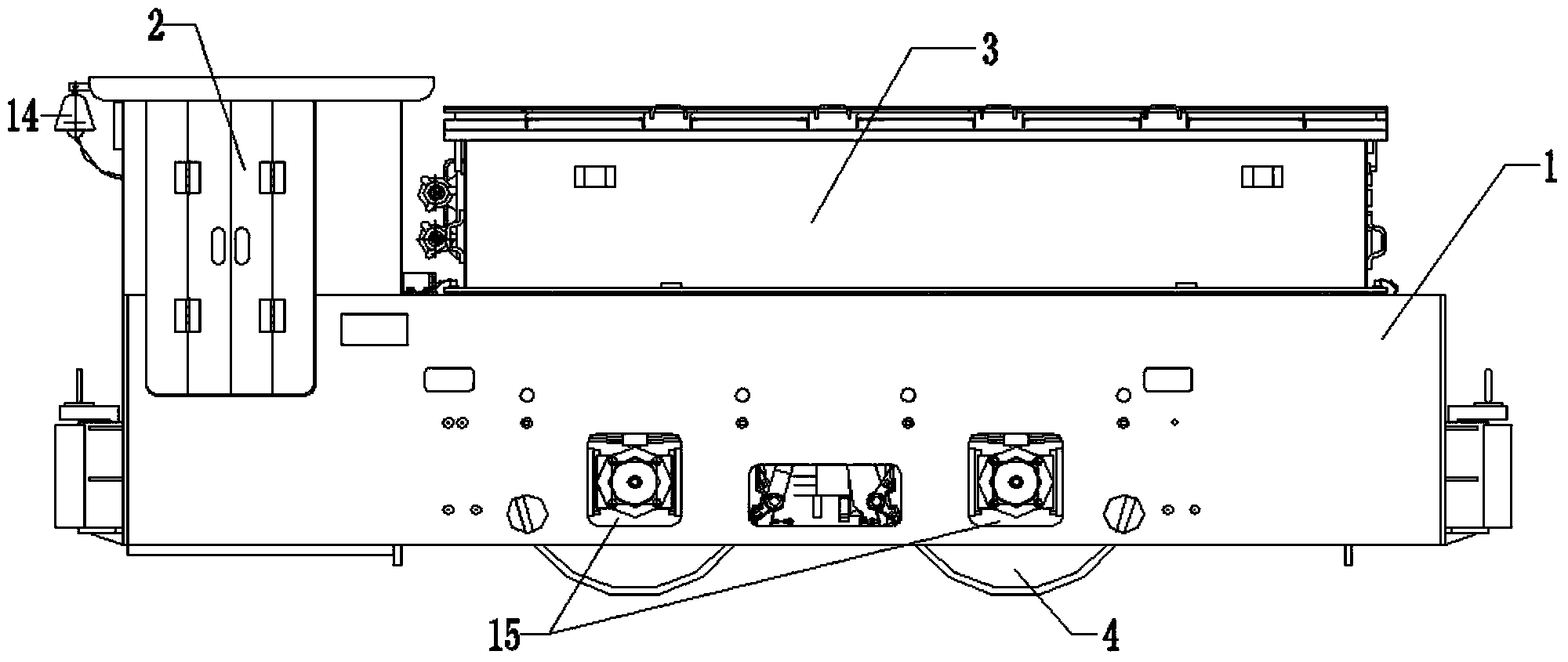
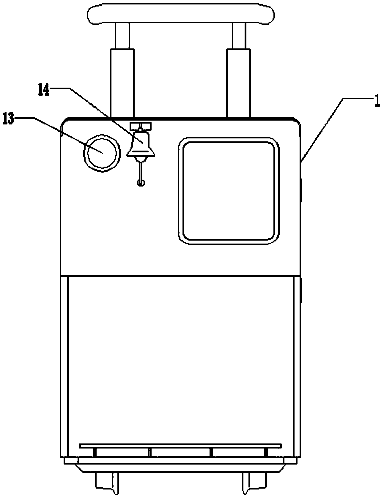
[0016] Such as figure 1 , figure 2 as well as image 3 As shown, the battery disc electric locomotive of the present invention includes a vehicle frame 1, and the vehicle frame 1 includes a frame structure formed by welding steel plates on both sides, a middle partition, two steel plates and a bottom steel plate, and one end of the vehicle frame 1 The driver's cab 2 is set, the battery 3 is set on the top of the vehicle frame 1, the battery 3 is fixed on the top of the vehicle frame 1 through a bracket, and the running device is installed on the bottom of the vehicle frame 1, and the running device includes two For wheels 4, axles 7, reduction boxes 5, elastic couplings 6, disc-type brushless DC traction motors 8, and two pairs of bearing housings 15 on both sides of the vehicle frame 1, the bearing housings 15 are floatingly connected to the g...


PUM


Abstract

The invention discloses an accumulator disc type electric locomotive. The electric locomotive comprises a frame, wherein one end of the frame is provided with a cab; an accumulator is arranged at the upper part of the frame; a walking device is mounted at the bottom of the frame, and is connected with a guiding plate bracket of the frame through bearing boxes at two ends; the walking device comprises one pair of wheels mounted on two sides of the frame, wheel shafts, bearing boxes at two ends of a locomotive shaft, gearboxes at the middle parts of the wheels, elastic couplings and disc type direct current brushless traction motors; the wheel shafts are connected with the output ends of the gearboxes; power input shafts of the gearboxes are connected with output shafts of the disc type direct current brushless traction motors through the elastic couplings; the disc type direct current brushless traction motors are connected to a direct current variable frequency speed regulator through signal transmission wires. Compared with the alternating current variable frequency locomotive vehicle promoted and applied at present, the accumulator disc type electric locomotive has the characteristics of large output torque, smoothness in speed regulation, quickness in electric braking response, short braking distance, high safety, no harmonic wave disturbance and low fault rate.

Description

technical field [0001] The invention relates to the technical field of electric locomotives, in particular to a battery disc electric locomotive. Background technique [0002] Now there are new types of chopper speed-regulating electric locomotives and AC variable-frequency speed-regulating electric locomotives on the market. However, for chopper speed-regulating electric locomotives, although they can steplessly adjust the speed, the motors used are still DC brushed motors. There are commutator copper bars and carbon brushes on the DC motor rotor that are easy to wear and tear; for AC variable frequency speed regulation electric locomotives, although the speed can be adjusted steplessly and there is no brush on the motor, the magnetic field still needs to be charged to establish. It is easy to generate harmonic interference, especially the underground interference to the communication network. Simultaneous starting is prone to shock. The braking of the two electric locomo...

Claims


Application Information

Patent Timeline
IPC IPC(8): B61C3/02
CPCY02T30/12Y02T30/00
Inventor 王保如周曙亮刘扬
Owner 安徽中车瑞达电气有限公司
Learn More