Multi-station automatic conveying mechanism for work-pieces

A transmission mechanism and multi-station technology, applied in conveyors, transportation and packaging, etc., can solve the problems of low market competitiveness, high manufacturing costs, and high labor costs, and achieve high work efficiency, fast response, and simple structure.

Inactive Publication Date: 2014-02-19
ZHANGJIAGANG XINXIN MOLDING
View PDF7 Cites 4 Cited by
  • Summary
  • Abstract
  • Description
  • Claims
  • Application Information

AI Technical Summary

Problems solved by technology

[0002] The processing of parts such as stamping parts or injection molding parts often needs to go through several machines to complete the processing of different parts. If the workpiece is sent to each station machine for processing manually, the efficiency is low on the one hand, and the labor cost is too high on the other hand. High, making the product manufacturing cost high and the market competitiveness low

Method used


Image

  • Multi-station automatic conveying mechanism for work-pieces
  • Multi-station automatic conveying mechanism for work-pieces

Examples


Embodiment 1

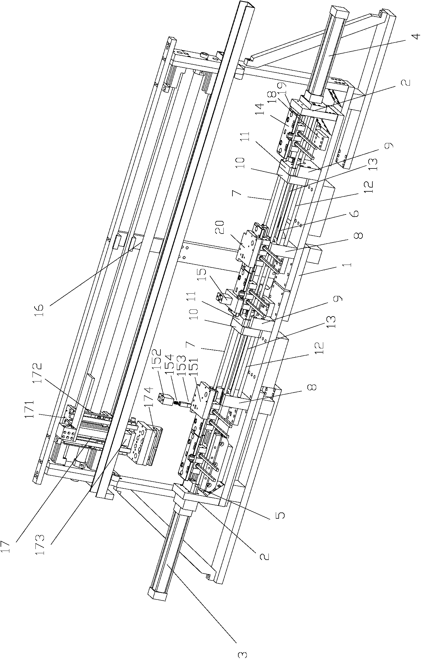
[0023] Example 1 as figure 1 As shown, a multi-station automatic transmission mechanism for workpieces includes a base 1, side plates 2 are arranged at both ends of the base 1, a left drive cylinder 3 and a right drive cylinder 4 are respectively arranged on the outside of the two side plates 2, and the left drive cylinder 3 pistons The end of the rod is provided with a left driving block 5, and the stroke of the left driving oil cylinder 3 is not less than the length of the workpiece in the conveying direction. The piston rod end of the right drive oil cylinder 4 is connected with a drive rod 6 . Two slide bars 7 are arranged between the two side plates, and the left drive block 5 is sleeved on the slide bars 7 . The slide bar 7 is provided with an initial station, several work stations arranged at intervals and an end station from left to right. The setting position of each processing machine needs to match with each work station.

[0024] Each work station on the base 1 ...

Embodiment 2

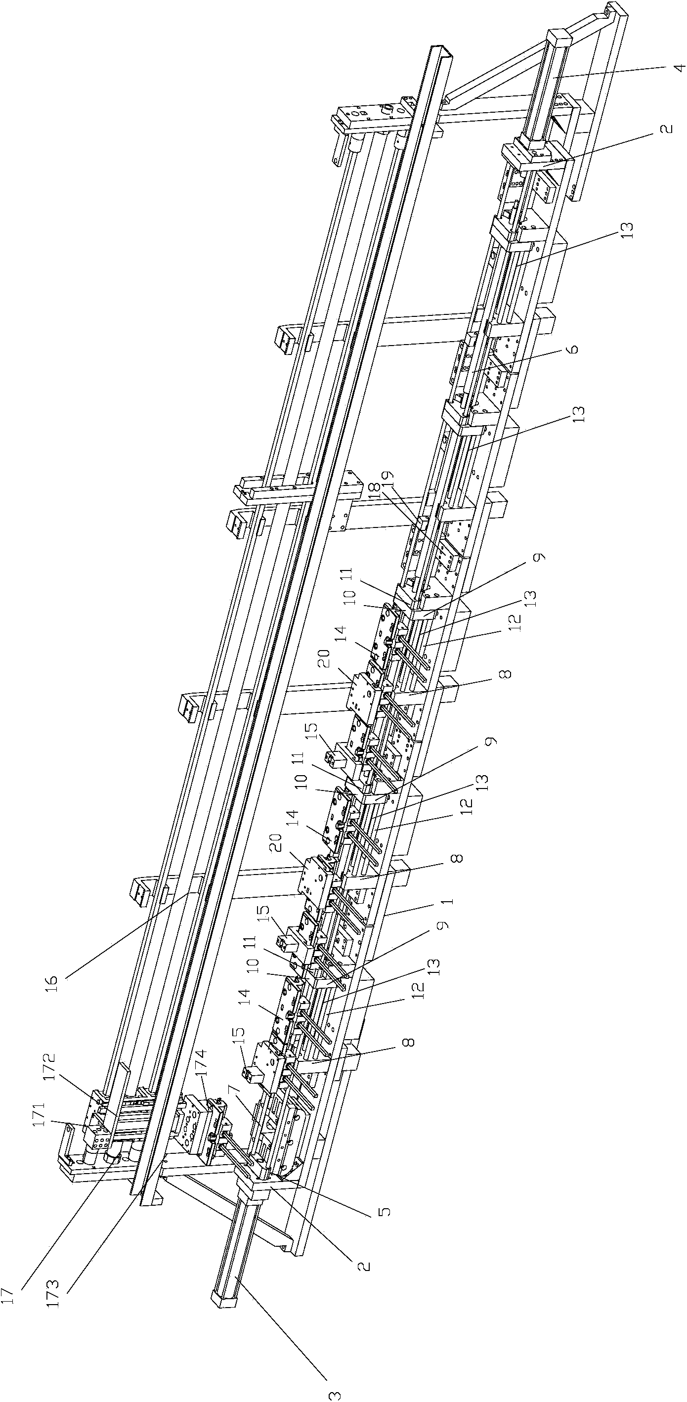
[0029] Example 2 as figure 2Shown is a transmission mechanism with five working stations for three-station transmission. Compared with Embodiment 1, the difference is that two more working stations are provided, and the tail stopper 19 is set at the third The right side of the working station, and the stroke of the transmission dolly 17 is adjusted to be applicable to the state of three stations.

[0030] The transmission mechanism needs to be used in conjunction with the workpiece feeding mechanism. If a push-type feeding mechanism is used, the single working cycle is: the right drive cylinder 4 is retracted, so that the left slider 10 and the right slider close to the left positioning block 8 on each working station 11 Push the workpiece clamping seat 14 on the station to move to the right until the left slider 10 touches the right positioning block 9. At this time, each right slider 11 pushes each adjacent workpiece clamping seat 14 to make the closest Each subsequent wor...


PUM


Abstract

The invention discloses a multi-station automatic conveying mechanism for work-pieces. The multi-station automatic conveying mechanism comprises a base. Side plates are arranged at the two ends of the base. A left driving oil cylinder and a right driving oil cylinder are arranged outside the two side plates respectively, a left driving block is arranged on the end portion of a piston rod of the left driving oil cylinder, the stroke of the left driving oil cylinder is left air cylinder stroke, and the piston rod end of the right driving oil cylinder is connected with a driving rod. Two sliding rods are arranged between the side plates and provided with initial stations, a plurality of work stations arranged at intervals and finishing stations from left to right. A left locating block, a right locating block, a left sliding block and a right sliding block are arranged on each work station on the base, the driving rod penetrates through the left locating blocks, the right locating blocks, the left sliding blocks and the right sliding blocks, the left sliding blocks and the right sliding blocks are arranged on the sliding rods in a sleeved mode and driven by the driving rod, the left sliding blocks and the right sliding blocks move to the left locating blocks when a piston rod of the right driving oil cylinder is pushed out, and the left sliding blocks and the right sliding blocks move to the right locating blocks when the piston rod of the right driving oil cylinder is retracted.

Description

technical field [0001] The invention relates to a workpiece multi-station automatic transmission mechanism. Background technique [0002] The processing of parts such as stamping parts or injection molding parts often needs to go through several machines to complete the processing of different parts. If the workpiece is sent to each station machine for processing manually, the efficiency is low on the one hand, and the labor cost is too high on the other hand. High, so that the product manufacturing cost is high, and the market competitiveness is low. If these machines are arranged side by side and equipped with a workpiece multi-station automatic transmission mechanism and an automatic feeding mechanism, the automatic processing of each processing procedure of the workpiece can be realized, the production efficiency can be greatly accelerated, and the manufacturing cost can be saved. Contents of the invention [0003] The technical problem to be solved by the present inv...

Claims


Application Information

Patent Timeline
IPC IPC(8): B65G25/02
Inventor 戴益新
Owner ZHANGJIAGANG XINXIN MOLDING
Why Eureka
Try Eureka