Shear force connecting part, combination beam comprising same and construction method of combination beam
A construction method and technology for connecting parts, which are applied in the directions of bridges, building components, bridge parts, etc., can solve the problems of unfavorable corrosion resistance of steel beams 40, loss of pre-tightening force of high-strength bolts 42, and loose connections, so as to ensure prestressed tension. effect, high application efficiency, and the effect of improving construction efficiency
- Summary
- Abstract
- Description
- Claims
- Application Information
AI Technical Summary
Problems solved by technology
Method used
Image

Examples
Embodiment 1
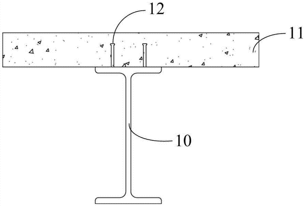
[0049] Example 1: Combining Figure 4 Explain that the shear connector 200 of the present invention is mainly used in the negative moment area of the composite structure continuous beam, and it includes a pre-embedded steel plate 201, and several sets of high-strength bolts that can be connected to the steel beam are arranged on the pre-embedded steel plate 201. Vice 100. The above-mentioned high-strength bolt connection pair 100 includes a bolt 102, a fastening nut 103 and a fastening nut 2 104 threaded on the bolt 102 and located on both sides of the embedded steel plate 201, and a washer 1 set on the bolt 102. 106 and spacer two 107. Wherein, gasket one 106 is located between fastening nut one 103 and embedded steel plate 201 , and gasket two 107 is located between fastening nut two 104 and embedded steel plate 201 . The fixed end of the bolt 102 is located on the steel beam, and the free end of the bolt 102 passes through the top plate of the steel beam and part of the...
Embodiment 2
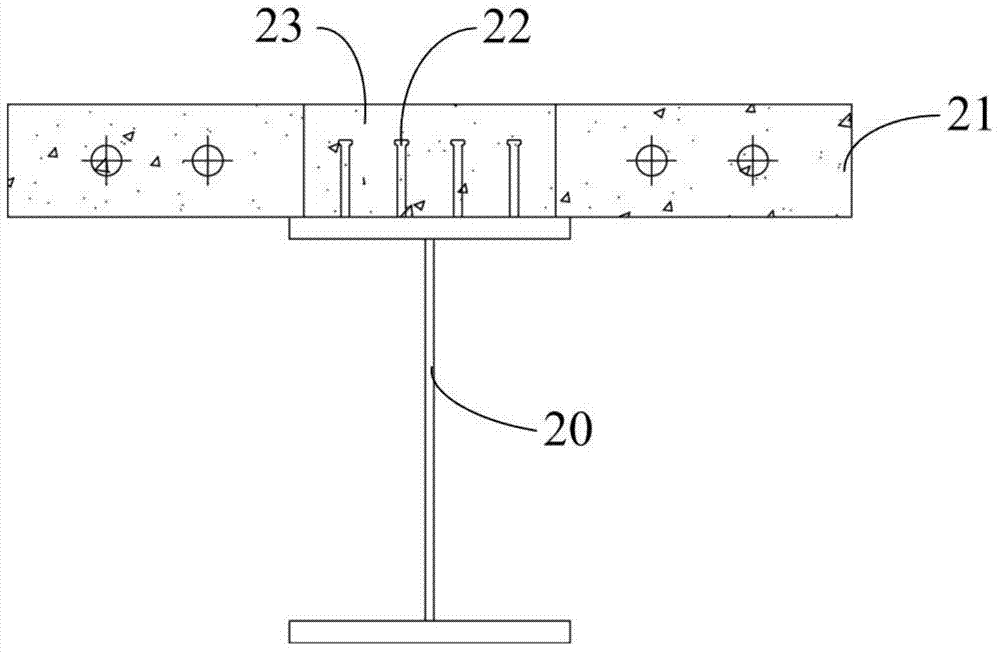
[0052] Embodiment two: combine Figure 5 The shear connector 300 of the present invention is different from the first embodiment in that the shear connector 300 of this embodiment also includes a steel beam 301, and the embedded steel plate 201 is connected to the steel beam by several sets of high-strength bolts. 301 connection.
[0053] Further, the width D1 of the embedded steel plate 201 is greater than the width D2 of the top plate of the steel beam 301 , and the supporting surface of the embedded steel plate 201 is large, so the force on the upper surface of the steel beam 301 is uniform.
[0054] The steel beam 301 is section steel, I-beam, steel box girder or steel truss girder, etc.
[0055] Furthermore, the contact surface of the pre-embedded steel plate 201 and the roof of the steel beam 301 adopts an anti-corrosion coating system that meets the requirements of the friction surface.
Embodiment 3
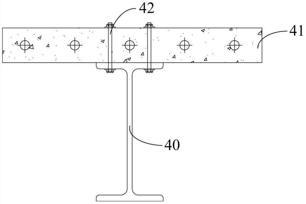
[0056] Example Three: Combining Figure 6 and Figure 7 A composite beam 400 with shear connectors of the present invention is illustrated, which includes a concrete slab 401 and several shear connectors 300 located at the lower part of the concrete slab 401 . The fixed end of the bolt 102 in the shear connector 300 is located on the bottom surface of the top plate of the steel beam 301 and is tightened and fixed by the fastening nut 103, and the free end of the bolt 102 passes through the top plate of the steel beam 301 and the pre-embedded steel plate 201 and is embedded in the concrete slab 401 . The drilling precision of the bolt holes of the embedded steel plate 201 and the steel beam 301 is the same as that of high-strength bolts. When the composite beam 400 is longer, the bolt holes can be appropriately enlarged according to the longitudinal deformation of the concrete slab 401 .
[0057] Such as Figure 6 As shown, the top surface of the embedded steel plate 201 is ...
PUM
 Abstract
Description
Claims
Application Information
 - Generate Ideas
- Intellectual Property
- Life Sciences
- Materials
- Tech Scout
- Unparalleled Data Quality
- Higher Quality Content
- 60% Fewer Hallucinations
Browse by: Latest US Patents, China's latest patents, Technical Efficacy Thesaurus, Application Domain, Technology Topic, Popular Technical Reports.
© 2025 PatSnap. All rights reserved.Legal|Privacy policy|Modern Slavery Act Transparency Statement|Sitemap|About US| Contact US: help@patsnap.com