Electric heating device and system

An electric heating device and electrode technology, applied in the coupling of optical waveguide, etc., can solve the problems of easy drift, narrow range of flame temperature adjustment, difficult to control, etc., achieve uniform and stable heating, avoid unstable and uniform, and convenient control

Inactive Publication Date: 2014-02-19
CENT SOUTH UNIV
View PDF3 Cites 7 Cited by
  • Summary
  • Abstract
  • Description
  • Claims
  • Application Information

AI Technical Summary

Problems solved by technology

However, flame heating inevitably has the following disadvantages: flame heating is unstable, disturbed by the environment, and easy to drift, resulting in poor performance consistency of optical fiber devices. It is also affected by the gas pressure in the tank, and the percentage of hydrogen and oxygen needs to be adjusted frequently ; The temperature adjustment range of the flame is narrow and difficult to control, and often fails to meet the expected requirements; flame heating will generate OH- ions, which will increase the loss of optical fiber devices when it enters the optical fiber, and reduce the reliability of the optical fiber; high-purity gas is not safe , and expensive

Method used


Image

  • Electric heating device and system
  • Electric heating device and system
  • Electric heating device and system

Examples


Embodiment Construction

[0037] Embodiments of the present invention will be further described in detail below in conjunction with the accompanying drawings and examples. The following examples are only used to illustrate the present invention, but can not be used to limit the scope of the present invention.

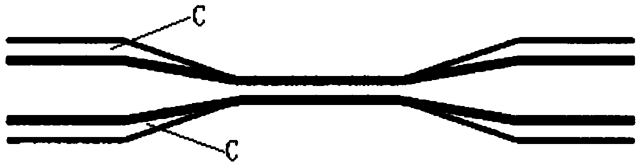
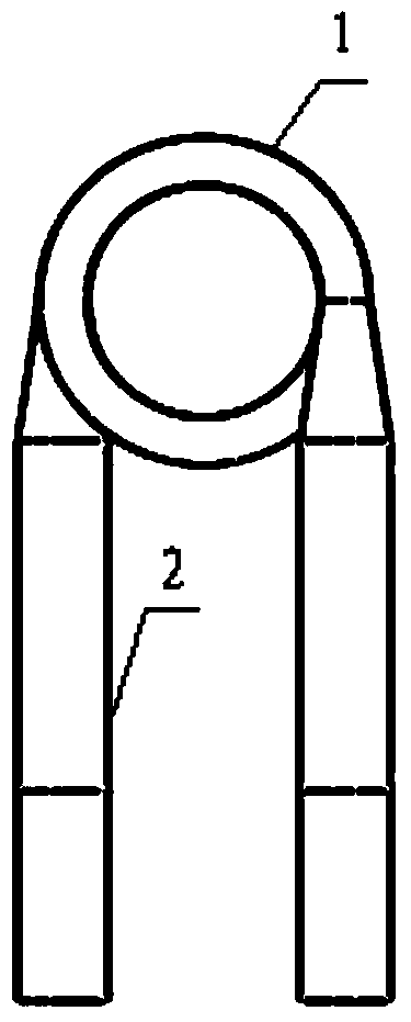
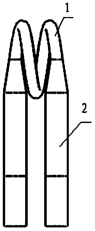
[0038] Figure 2 to Figure 8 The structure of the electric heating device of a preferred embodiment of the present invention is shown. As shown in the figure, the electric heating device of the present invention includes a heating element 1, two electrodes 2 and a ceramic shell 3, and the two electrodes 2 are connected to both ends of the heating element 1; a cavity 31 is formed inside the ceramic shell 3 to generate heat. The body 1 is placed in the cavity 31; the top of the ceramic shell 3 forms a notch 32 that runs through the thickness direction of the ceramic shell 3 and communicates with the cavity 31. The heating element 1 has a helical structure, and the position of the helical structur...


PUM


Abstract

The invention discloses an electric heating device and system. The device comprises a heating body, two electrodes and a ceramic shell, wherein the two electrodes are connected to the two ends of the heating body, a cavity is formed inside the ceramic shell, the heating body is placed in the cavity, a notch which penetrates through the thickness direction of the ceramic shell and is communicated with the cavity is formed in the top of the ceramic shell, and the heating body is of a spiral structure. Due to the position of the spiral structure, the spiral axis of the spiral structure is approximately perpendicular to the extending direction of the notch from top to bottom, and a pair of twisted optical fibers extending in the thickness direction of the ceramic shell can enter the position between two spiral rings of the spiral structure downwards from the notch. Due to the facts that the electric-heating mode is adopted in the electric heating device, the heating body is of the spiral structure and is clamped by the ceramic shell, and the optical fibers are heated between the two spiral rings of the spiral structure, heating is even and stable, and the defect that flame heating is not stable or even enough is overcome. Meanwhile, temperature heat stress and structural heat stress are distributed reasonably, and positions with stress concentration do not exist.

Description

technical field [0001] The invention relates to electric heating technology, in particular to an electric heating device and system for melting tapers. Background technique [0002] Fused tapered optical fiber device is the most representative of optical fiber devices and a basic device that constitutes other devices, and its corresponding manufacturing process is fused tapered technology. Fused tapered technology can be applied to various optical passive devices, such as optical fiber couplers, optical wavelength division multiplexers, optical fiber reflectors, optical fiber polarization beam splitters, optical attenuators, etc. [0003] At present, the heating system for fusion tapering generally adopts the flame heating method. The basic process is as follows: two single-mode optical fibers with the coating layer removed are brought together, heated and melted under a high-temperature flame, and stretched to both sides at the same time to produce A two-way conical struct...

Claims


Application Information

Patent Timeline
IPC IPC(8): G02B6/255
Inventor 郑煜李文娟段吉安周剑英吕文王丽军李继攀
Owner CENT SOUTH UNIV
Why Eureka
Try Eureka