
Earth plasmasphere dynamic tracking imager

A plasma layer, dynamic tracking technology, applied in instruments, image communication, television, etc., can solve problems such as low image quality and limited imaging viewing angle

Inactive Publication Date: 2014-02-19
CHANGCHUN INST OF OPTICS FINE MECHANICS & PHYSICS CHINESE ACAD OF SCI
View PDF1 Cites 4 Cited by
  • Summary
  • Abstract
  • Description
  • Claims
  • Application Information

AI Technical Summary

Problems solved by technology

[0003] The purpose of the present invention is to propose a dynamic tracking imager for the earth's plasma layer, which solves the problems of low image quality and limited imaging viewing angles caused by image stitching or scanning imaging in the prior art, and realizes global imaging of the earth's plasma layer

Method used


Image

  • Earth plasmasphere dynamic tracking imager
  • Earth plasmasphere dynamic tracking imager
  • Earth plasmasphere dynamic tracking imager

Examples


Embodiment Construction

[0018] Embodiments of the present invention will be further described below in conjunction with the accompanying drawings.

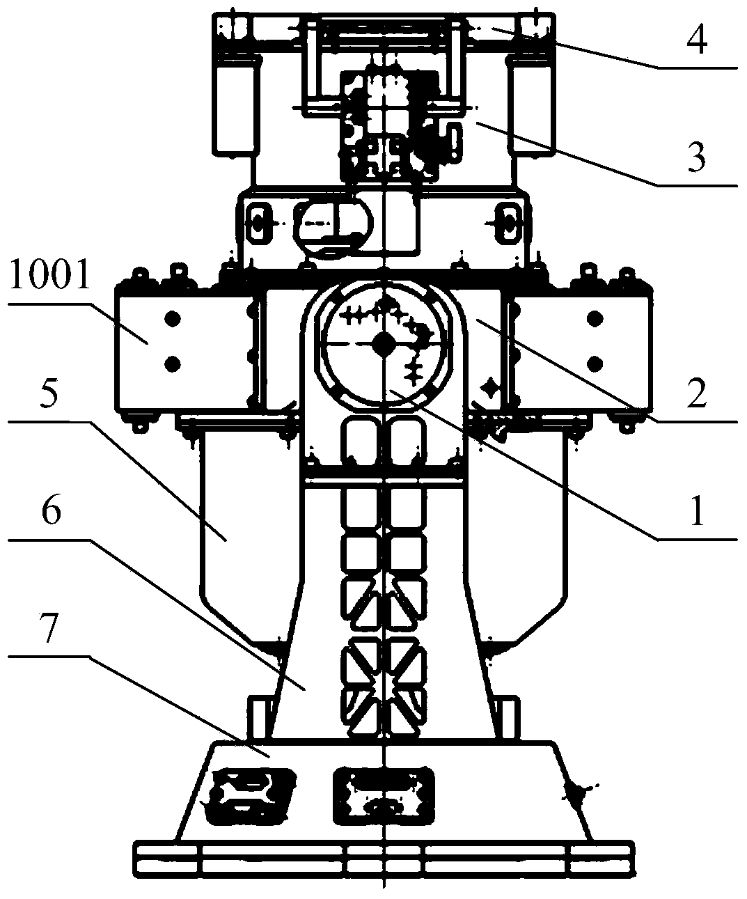
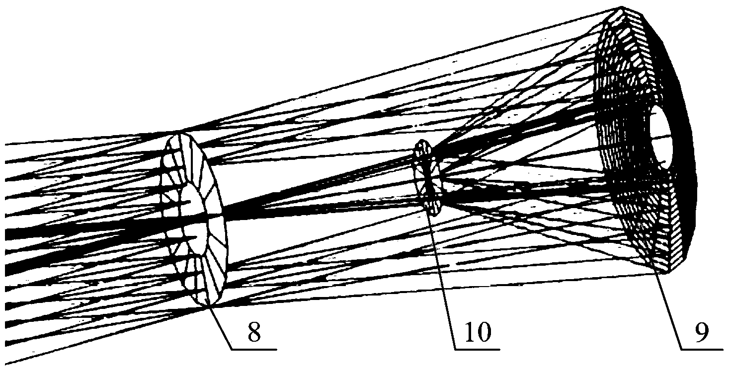
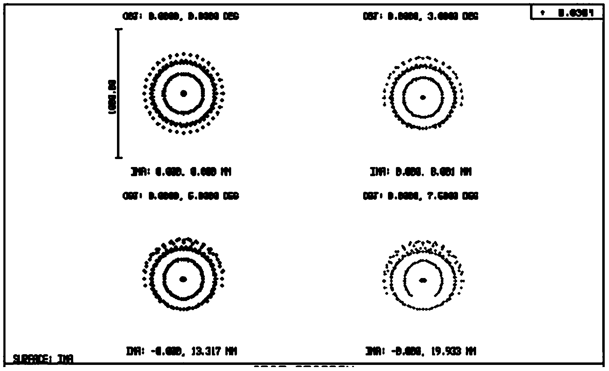
[0019] See attached figure 1 , attached figure 2 And attached image 3 , a dynamic tracking imager for the earth's plasma layer of the present invention includes an optical subsystem and a mechanical structure subsystem;

[0020] The optical subsystem includes an annular optical entrance pupil 8, a photon counting detector 10, and a spherical EUV multilayer mirror 9 arranged in sequence along the optical axis. At the center of curvature of the layered mirror 9, the light is irradiated to the spherical EUV multilayer mirror 9 through the annular optical entrance pupil 8, and after being reflected by the spherical EUV multilayer mirror 9, it passes through the photon counting detector 10 receive imaging;

[0021] The mechanical structure subsystem includes an EUV camera imaging system and a two-dimensional rotation system. The EUV camera imaging syste...


PUM


Abstract

The invention discloses an earth plasmasphere dynamic tracking imager, and belongs to the technical field of space weather monitoring. The earth plasmasphere dynamic tracking imager aims at solving the problem that in the prior art, earth plasmasphere overall-situation imaging can not be achieved, and comprises an optical system and a mechanical structure system, wherein the optical system comprises an annular optical entrance pupil, an image receiver and a spherical surface pole ultraviolet multi-film reflection mirror, and the optical imaging function of an earth plasmasphere at the 30.4nm wave band is mainly achieved. The mechanical structure system comprises an EUV camera imaging system and a two-dimensional rotary system, the EUV camera imaging system achieves the functions of installing, supporting and protecting the optical system and the like, and the two-dimensional rotary system achieves orientation and pitching adjustment on view angles of the EUV camera imaging system. After the earth plasmasphere dynamic tracking imager reaches an imaging track along with a spacecraft, image motion compensation to satellite motion and dynamic tracking imaging on an object during imaging are achieved through the two-dimensional rotary system, and multi-angle and high-quality overall-situation imaging on the object is achieved.

Description

technical field [0001] The invention belongs to the technical field of space weather monitoring, and in particular relates to a dynamic tracking imager for the earth's plasma layer. Background technique [0002] As the most important active area of ​​the inner magnetosphere, the distribution and evolution of the Earth's plasma layer has an extremely important impact on the Earth and its space environment, and has important research value. Currently, global imaging of the Earth's plasmasphere has not been truly realized. The Planet-B satellite launched by Japan in 1998 stitched one-dimensional images of different light intensities into two-dimensional images, but the time resolution was too poor to be a true two-dimensional imaging; the United States launched IMAGE (Magnetic Top to Aurora Global The extreme ultraviolet camera carried by the satellite imager) realizes the two-dimensional imaging of the earth's plasma layer for the first time, but because there is no tracking ...

Claims


Application Information

Patent Timeline
Patent Type & Authority Applications(China)
IPC IPC(8): G03B17/12G03B17/17G02B27/64H04N5/225
Inventor 陈波何玲平刘世界何飞李朝辉
Owner CHANGCHUN INST OF OPTICS FINE MECHANICS & PHYSICS CHINESE ACAD OF SCI
Learn More