Image ring artifact correcting method

A ring artifact and correction method technology, applied in the field of medical image processing, can solve the problems of increasing the pixel value error of pixel points in normal areas, image distortion, and unsatisfactory correction results, avoiding data interpolation and distortion, and achieving high image processing speed. Effect

Inactive Publication Date: 2014-02-19
SOUTHERN MEDICAL UNIVERSITY
View PDF5 Cites 17 Cited by
  • Summary
  • Abstract
  • Description
  • Claims
  • Application Information

AI Technical Summary

Problems solved by technology

There are three disadvantages in this method: first, only by calculating the variance of the pixel values ​​in each sample space is less than the predetermined threshold as the criterion for identifying artifacts is obviously insufficient, because the pixels in the normal area of ​​the same medium may also meet the variance less than Predetermined threshold, the subsequent correction of pixels in the normal area is obviously a waste of processing time and increases the pixel value error of the pixels in the normal area; second, because the pixel value of the artifact point itself is inaccurate, then the above-mentioned "sample space The pixel value of each pixel point in the vertical axis is replaced by the average pixel value of the pixel point and the pixel point between the two artifacts in the vertical axis direction to eliminate the ring artifact. Obviously, the error information of the artifact point is brought into the final correction. In the results, especially when the artifacts are quite different from the surrounding pixel areas, the correction results are not ideal; third, the coordinate transformation itself has interpolation calculations, which cause image distortion

Method used


Image

  • Image ring artifact correcting method
  • Image ring artifact correcting method
  • Image ring artifact correcting method

Examples


Embodiment Construction

[0028] Embodiments of the present invention are described in detail below:

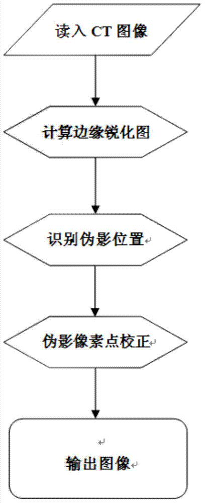
[0029] Such as Figure 1-4 As shown, the image ring artifact correction method of the present invention comprises the following steps:

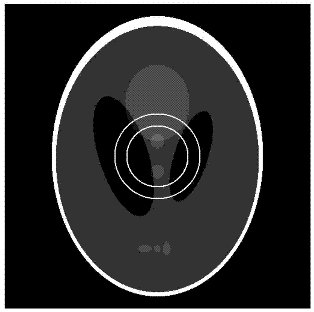
[0030] S1: read in an initial image, the initial image is a matrix of pixel points I(i, j) with M rows and N columns, where (i, j) is the coordinates of the pixel point I;

[0031] Specifically, the initial image has ring artifacts. In this embodiment, the size of the initial image is 511 rows and 511 columns, that is, M=N=511, i=1, 2, 3, 4...n,... 511, j=1, 2, 3, 4...n,...511.

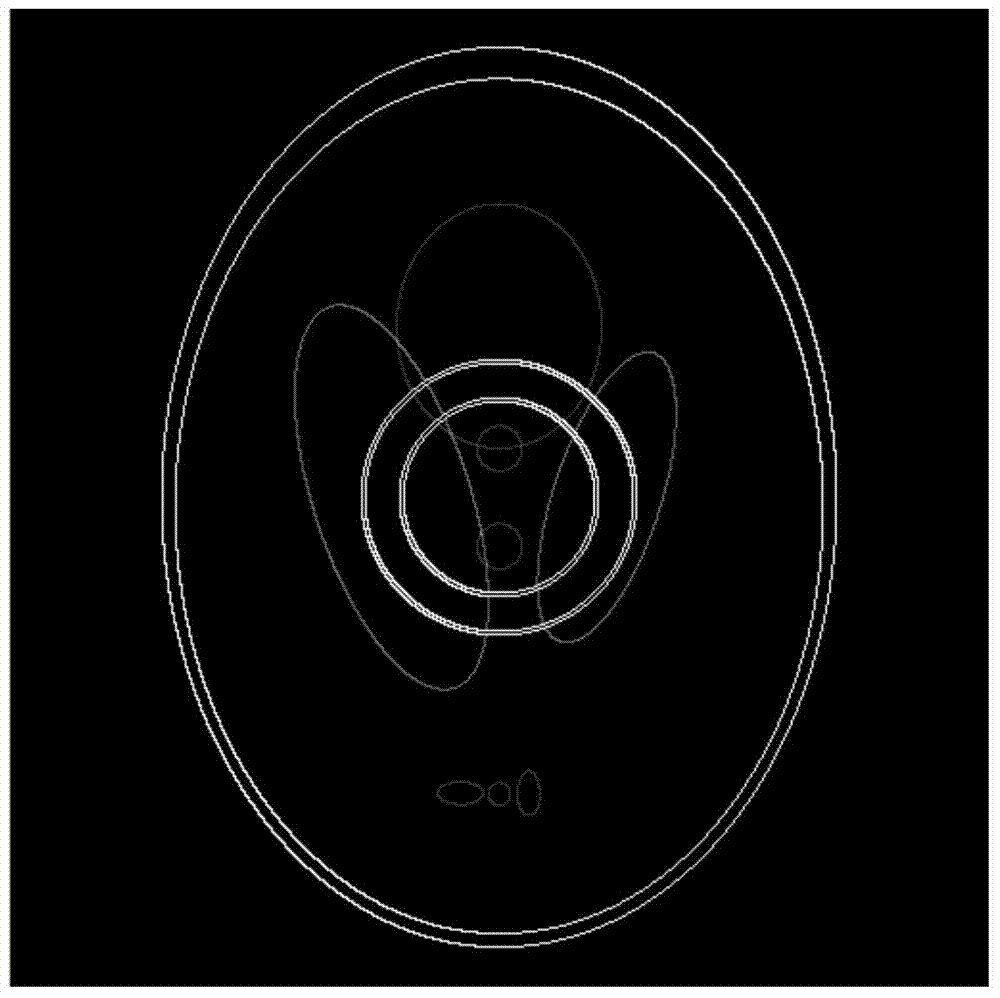
[0032] S2: Calculate the edge-sharpened image g(i,j) of the initial image, and extract the center point C(T,S) of the edge-sharpened image g(i,j), where T is the center point C located at pixel point I (i, j) the row of the matrix, S is the center point C is located in the column of the pixel point I (i, j) matrix;

[0033] Specifically, the method of calculating the edge-sharpened imag...


PUM


Abstract

The invention discloses an image ring artifact correcting method. The method comprises the step of reading an original image which is a matrix of a pixel point located at the Mth line and the Nth row; the step of calculating an edge sharpening image of the initial image and extracting the central point of the edge sharpening image; the step of respectively extracting at least three strings of data from the edge sharpening image in at least three directions with the central point as the starting point, arranging the three strings of data in the A direction in an aligned mode and aligning the central points of the three strings of data to form a plurality of sets of data in the B direction perpendicular to the A direction; the step of calculating the average value u and the variance t of each set of data in the B direction, comparing the average value u with the first threshold d1 and comparing the variance t with the second threshold d2, wherein if u <d1, the set of data are skipped, and if t<d2, at least one serial number pair of the set of data in the three strings of data is recorded; the step of calculating the external diameter and the internal diameter of a ring artifact corresponding to the serial number pair according to the serial number pair; the step of correcting the pixel value in the ring artifact in the area where the external diameter and the internal diameter are located and outputting the corrected image.

Description

technical field [0001] The invention relates to medical image processing technology, and particularly designs an image ring artifact correction method. Background technique [0002] In medical diagnosis, it is often necessary to obtain an image by taking pictures of the affected area, and then analyze it. Among them, CT technology has been widely used in many fields of medical diagnosis. Artifacts are an important factor restricting the quality of CT images and affecting clinical diagnosis, and ring artifacts are a common artifact in CT. There are many factors that produce ring artifacts, among which the inconsistency of the detector element response on the detector is the most common. From the appearance of the ring artifact on the CT image, it is a series of concentric rings with a certain width, which are centered on the center of the CT image and whose gray scale is different from the surrounding pixels. The existence of ring artifacts brings great troubles to further...

Claims


Application Information

Patent Timeline
Patent Type & Authority Applications(China)
IPC IPC(8): G06T5/00
Inventor 周凌宏齐宏亮李慧君徐圆
Owner SOUTHERN MEDICAL UNIVERSITY
Why Eureka
Try Eureka