Low-voltage vacuum energy-saving normally-open direct-current contactor

A technology of DC contactors and contactors, applied in high-voltage air circuit breakers, high-voltage/high-current switches, relays, etc., can solve problems such as temperature rise, inability to adapt, and large power consumption, so as to reduce temperature rise and save electric energy The effect of consumption and prolonging the service life

Inactive Publication Date: 2014-02-19
ZHENJIANG TIANXIANG PRECISION ELECTRIC MACHINERY
View PDF5 Cites 6 Cited by
  • Summary
  • Abstract
  • Description
  • Claims
  • Application Information

AI Technical Summary

Problems solved by technology

However, when the existing DC contactor works, the coil current always maintains the large current required for starting, resulting in large power consumption and temperature rise, and cannot adapt to the workplace with strict temperature rise requirements.

Method used


Image

  • Low-voltage vacuum energy-saving normally-open direct-current contactor
  • Low-voltage vacuum energy-saving normally-open direct-current contactor
  • Low-voltage vacuum energy-saving normally-open direct-current contactor

Examples


Embodiment Construction

[0024] The invention will be further described below in conjunction with the drawings:

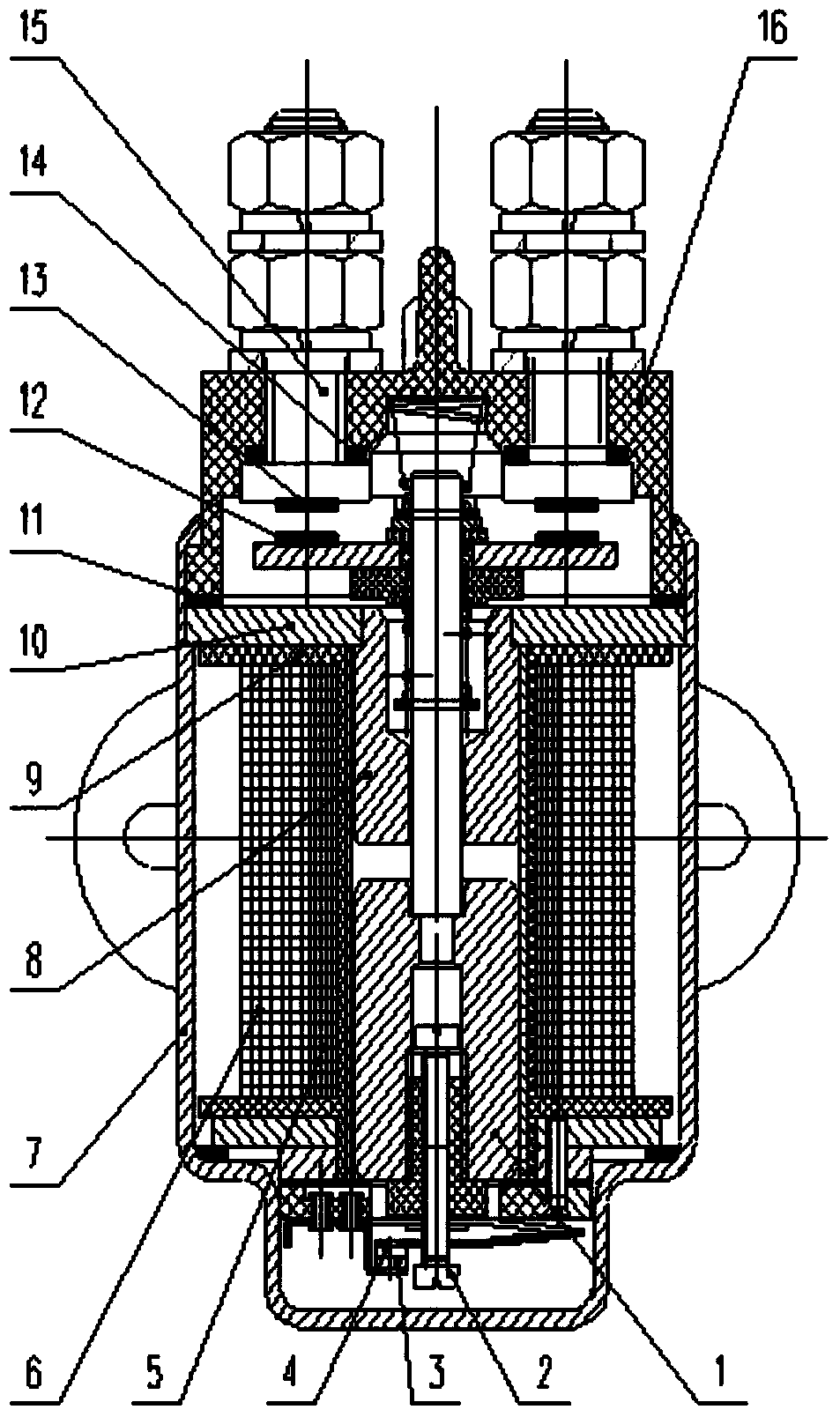
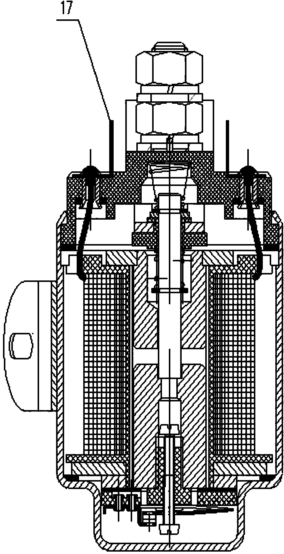
[0025] figure 1 Is a schematic diagram of the invention

[0026] A low-voltage vacuum energy-saving normally open DC contactor includes a main contact terminal 15 with a main static contact 13 provided at the bottom of the main contact terminal 15 and an active contact 12 and a moving contact 12 below the main static contact 13 They are respectively arranged on the left and right sides of the ejector rod; the ejector rod connects the moving iron core 1 and the static iron core 8 in turn from top to bottom. The upper end of the moving iron core 1 is fixed in the middle of the horizontal fixed plate 10, the moving iron core 1 and the static iron A coil bobbin 9 is arranged outside the core 8, the inner starting coil 5 is wound on the coil bobbin 9, and the upper part of the coil bobbin 9 is a fixed plate 10;

[0027] The fixed plate 10 and the coil housing 7 form a lower cavity, and a structure co...


PUM


Abstract

The invention provides a low-voltage vacuum energy-saving normally-open direct-current contactor which comprises main contact binding posts (15), main fixed contacts (13), main movable contacts (12), a movable iron core (1), a fixed iron core (8), a contactor body (16) and springs, and further comprises outer-layer maintaining attraction coils (6), inner-layer starting coils (5), coil movable contacts (4) and coil fixed contacts (3). The main movable contacts (12) are arranged below the main fixed contacts (13). The springs maintain the disconnected states of the main fixed contacts (13) and the main movable contacts (12). The coil movable contacts (4) and the coil fixed contacts (3) are arranged at the lower end of the inner-layer starting coils (5). When the low-voltage vacuum energy-saving normally-open direct-current contactor is started, a current directly enables the movable iron core (1) and the fixed iron core (8) to be attracted through the inner-layer starting coils (5), the coil movable contacts (4) and the coil fixed contacts (3) are disconnected through screws (2), and an upper cavity and a lower cavity are both vacuum space. According to the low-voltage vacuum energy-saving normally-open direct-current contactor, the current is reduced, electric energy consumption is saved, the temperature rising of the contactor is reduced, oxidation and burning loss caused by electric arcs to the contacts are reduced, and the service life of the contacts is prolonged.

Description

Technical field [0001] The invention relates to a direct current contactor, particularly a low-voltage vacuum energy-saving direct current contactor. Background technique [0002] The function of the DC contactor is to disconnect the DC power supply, such as the battery, from the DC load, such as the DC motor, when there is electricity. It is already a mature product. However, when the existing DC contactor is working, the coil current always maintains the large current required for starting, resulting in large power consumption and temperature rise, and it cannot be adapted to work occasions that require strict temperature rise. Summary of the invention [0003] Technical problems to be solved: [0004] When the DC contactor is working, the coil current is large and the temperature rises. When disconnecting the circuit, reduce the current through the load. [0005] Technical solutions: [0006] In order to achieve the above functions, the present invention provides a low-voltage v...

Claims


Application Information

Patent Timeline
Patent Type & Authority Applications(China)
IPC IPC(8): H01H33/66H01H50/56H01H50/44
Inventor 赵天林赵玉山耿俊丹高景成
Owner ZHENJIANG TIANXIANG PRECISION ELECTRIC MACHINERY
Why Eureka
Try Eureka