Variable displacement control mode of motor mover with unequal interval

A displacement control and mover technology, applied in electric components, electrical components, electromechanical devices, etc., can solve problems such as large fluctuations, unstable operation, reduction of electromagnetic resultant force, etc., to eliminate the possibility of electromagnetic thrust in the opposite direction, reduce The effect of controlling difficulty, eliminating possibility

Active Publication Date: 2015-09-30
TAIYUAN UNIV OF TECH
View PDF4 Cites 0 Cited by
  • Summary
  • Abstract
  • Description
  • Claims
  • Application Information

AI Technical Summary

Problems solved by technology

The single-phase mover winding energization control method has the problems of small electromagnetic thrust of the mover, large fluctuations, and unstable operation. The patent "direct drive switched reluctance planar motor mover displacement control method (ZL201210060243.5)" belongs to " Single-phase-two-phase” mover windings and other interval positioning displacement control methods, single-phase and two-phase mover windings are energized in turn, and the displacements in the operating intervals are equal. There are two problems in this control method: first, the single-phase windings are energized After the end, the mover should run to the position where the centerline of the mover teeth of one of the three phases coincides with the centerline of the stator slot. At this time, the two-phase mover windings should be energized, which requires precise control of the power-on time. If the energization time of the mover winding is too short, the mover will not move to the position. At this time, if the two-phase mover winding is energized, one of the mover windings will generate a reverse electromagnetic thrust opposite to the moving direction of the mover. , resulting in a decrease in the resultant electromagnetic force, or even zero resultant force, making the mover unable to move
In short, compared with the single-phase mover winding control method, the "single-phase-two-phase" mover winding and other interval positioning displacement control methods increase the electromagnetic thrust, but there are still problems of unstable operation and poor reliability. Meet the requirements of high speed, high stability and high reliability of direct drive switched reluctance planar motor

Method used


Image

  • Variable displacement control mode of motor mover with unequal interval
  • Variable displacement control mode of motor mover with unequal interval
  • Variable displacement control mode of motor mover with unequal interval

Examples


Embodiment approach 1

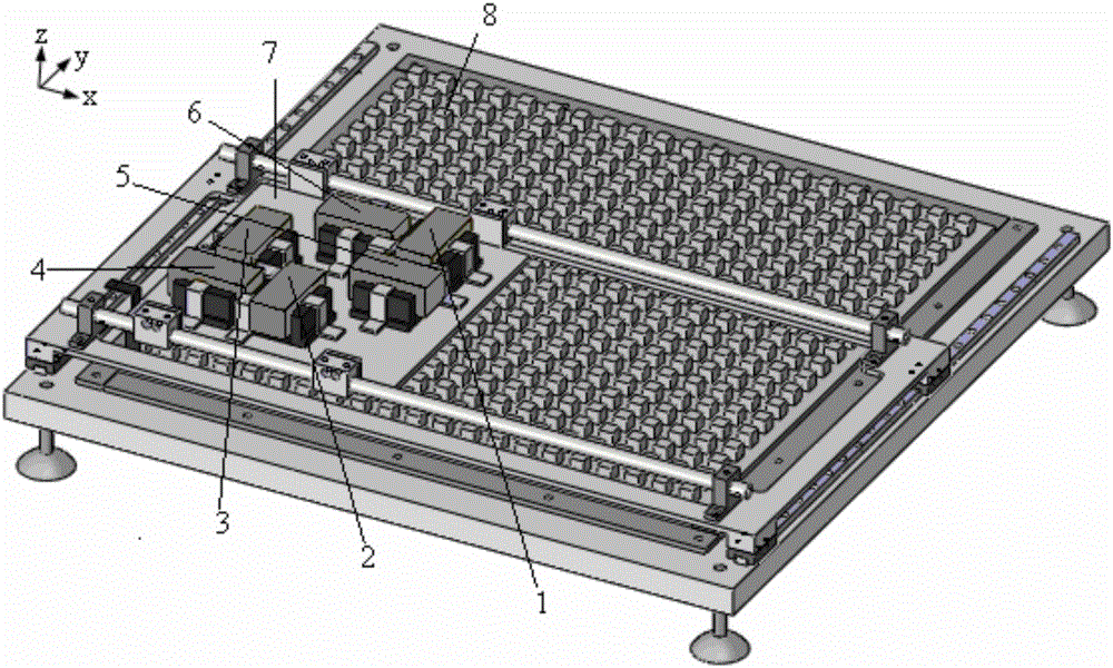
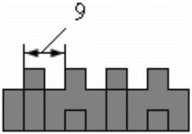
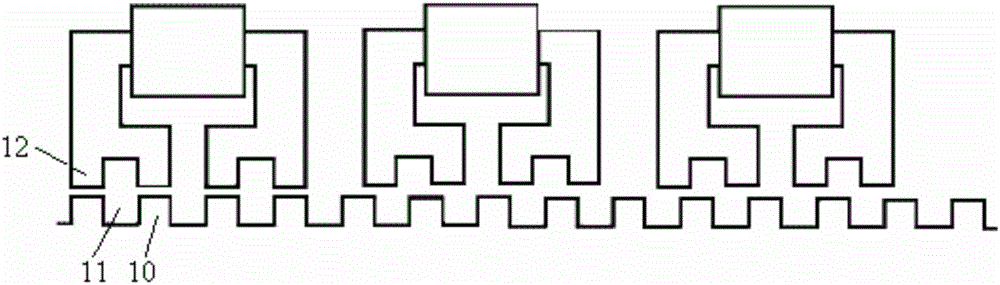
[0036] The displacement movement of the mover 7 changes periodically, and the movement cycle is equal to the stator pole distance 9, which is 12mm. Each cycle is divided into six operating intervals, and the six different positions of the mover 7 relative to the stator 8 determine the mover. energized state of the sub-winding.

[0037] See Table 2 for the energization sequence of the mover windings when the mover 7 moves to the right or to the left in the x direction.

[0038] Table 2 When the stator pole pitch is 6mm, the "single-phase-two-phase" variable displacement control rotor winding energization sequence

[0039] area

Position range (mm)

Power-on phase sequence when moving to the right

Power-on phase sequence when moving left

1

0~3

X C

X B

2

3~4

x C 、X B

x B 、X C

3

4~7

X B

X C

4

7~8

x B 、X A

x C 、X A

5

8~11

X A

X A

6

11~12

x...

Embodiment approach 2

[0051] The displacement movement of the mover 7 changes periodically, and the movement cycle is equal to the stator pole distance 9, which is 24mm. Each cycle is divided into six operating intervals, and the mover 7 is determined by six different positions of the mover 7 relative to the stator 8. energized state of the sub-winding.

[0052] See Table 3 for the energization sequence of the mover windings when the mover 7 moves to the right or to the left in the x direction.

[0053] Table 3. "Single-phase-two-phase" variable displacement control rotor winding energization sequence when the stator pole pitch is 24mm

[0054] area

Position range (mm)

Power-on phase sequence when moving to the right

Power-on phase sequence when moving left

1

0~5

X C

X B

2

5~8

x C 、X B

x B 、X C

3

8~13

X B

X C

4

13~16

x B 、X A

x C 、X A

5

16~21

X A

X A

6

21~24...

Embodiment approach 3

[0063] The displacement movement of the mover 7 changes periodically, and the movement cycle is equal to the stator pole distance 9, which is 36mm. Each cycle is divided into six operating intervals, and the mover 7 is determined by six different positions of the mover 7 relative to the stator 8. energized state of the sub-winding.

[0064] When the mover 7 moves to the right or to the left in the x direction, the sequence of electrification of the mover windings is shown in Table 4.

[0065] Table 4 When the stator pole pitch is 36mm, the "single-phase-two-phase" variable displacement control rotor winding energization sequence

[0066] area

Position range (mm)

Power-on phase sequence when moving to the right

Power-on phase sequence when moving left

1

0~9

X C

X B

2

9~12

x C 、X B

x B 、X C

3

12~21

X B

X C

4

21~24

x B 、X A

x C 、X A

5

24~33

X A

X A ...


PUM


Abstract

The invention discloses a motor rotor unequal interval variable displacement control mode, and belongs to the field of electromechanical control study. The motor rotor unequal interval variable displacement control mode is characterized in that when a single-phase rotor winding is powered up, a rotor 7 moves one fourth a stator polar distance 9; when two phase windings are powered up at the same time, the rotor 7 moves one twelfth the stator polar distance 9. The time that the single-phase rotor winding is powered up is longer than the time that the two phase rotor windings are powered up at the same time, so that it is guaranteed that electromagnetic force with the direction being the same as the moving direction can be generated by both the power-on two phase rotor windings within the power-on range, the possibility that reverse direction electromagnetic force can be generated by one of the two phases is removed, control difficulty is lowered, resultant force is increased, and efficiency is improved; on the other hand, the rotor traveling distance when the single-phase rotor winding is powered up is larger than the rotor traveling distance when the two phase rotor windings are powered up at the same time, it is guaranteed that all rotor teeth 12 of the power-on two phases do not align stator slots 11 when the two phase rotor windings are powered up at the same time, and therefore the condition that the electromagnetic force generated by one of the phase windings is zero can be avoided.

Description

technical field [0001] The invention relates to a motor mover unequal interval variable displacement control method, which belongs to the field of electromechanical control research, and specifically relates to a direct-drive switched reluctance that can overcome the reduction of electromagnetic thrust when the mover winding commutates, thereby ensuring the maximum electromagnetic resultant force A technical solution for the displacement control of planar motor movers. Background technique [0002] Direct-drive switched reluctance planar motors can be used in planar welding machines, large-scale integrated circuit processing and packaging, printed circuit board production, probe monitors, planar measuring instruments, robot drives and other fields. Due to the complexity of the structure and arrangement of the stator and mover of the direct-drive switched reluctance planar motor, in order to achieve high-precision positioning requirements, the movement of the mover must be pr...

Claims


Application Information

Patent Timeline
Patent Type & Authority Patents(China)
IPC IPC(8): H02K41/03
Inventor 陈燕马春燕李更新王颖
Owner TAIYUAN UNIV OF TECH
Why Eureka
Try Eureka