LED driving circuit

A technology of LED drive and LED array, applied in the direction of electric lamp circuit layout, electric light source, lighting device, etc., can solve the problems of lower conversion efficiency, large conduction resistance, and power consumption, and achieve low power consumption, high power factor, The effect of improving conversion efficiency

Active Publication Date: 2014-02-19
ZHEJIANG UNIV
View PDF7 Cites 19 Cited by
  • Summary
  • Abstract
  • Description
  • Claims
  • Application Information

AI Technical Summary

Problems solved by technology

However, there are two problems with this method. One is that the size of the LED current is determined by the reference voltage and the negative feedback circuit composed of the operational amplifier and the NMOS tube, so there is a certain deviation.
Another problem is that the current of each string of LEDs flows to the ground through the NMOS tube working in the saturation area, and the on-resistance of the NMOS tube in the saturation area is larger than that of the NMOS tube in the linear area, so there is power consumption in the NMOS tube, which reduces the conversion efficiency
[0006] In summary, the existing technology has problems in terms of conversion efficiency, power factor and reliability

Method used


Image

  • LED driving circuit
  • LED driving circuit
  • LED driving circuit

Examples


Embodiment Construction

[0044] In order to describe the present invention more specifically, the technical solutions and related principles of the present invention will be described in detail below in conjunction with the accompanying drawings and specific embodiments.

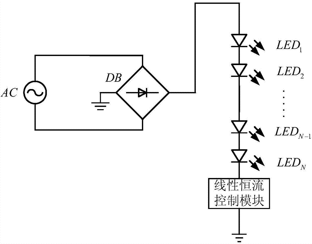
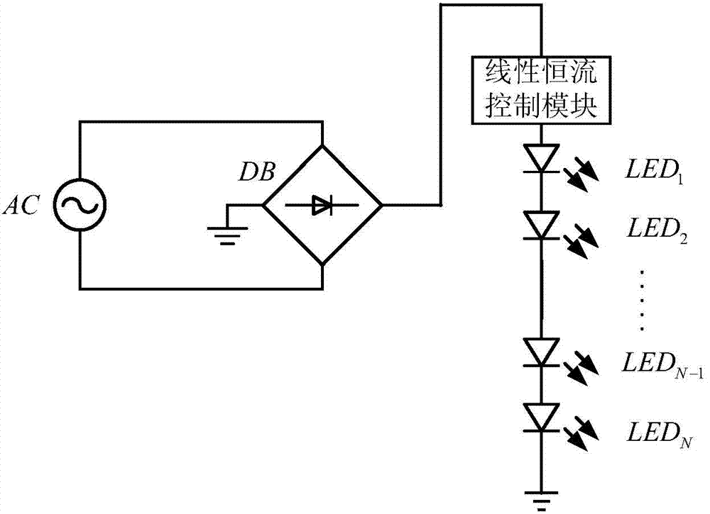
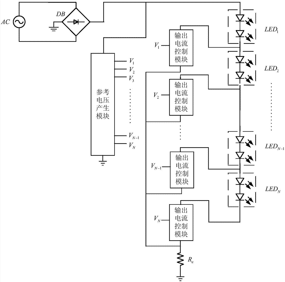
[0045] like Figure 4As shown, the LED driving circuit is connected to the LED array, the LED array is an N-dimensional square matrix, and N is a natural number greater than 1; the LED array is formed by connecting N groups of identical LED lamps in series and in parallel, and the LED driving circuit includes a current source module, Voltage divider circuit module, comparison circuit module, logic control module, switch module and bias circuit module;

[0046] The current source module is used to provide constant current power for the LED array;

[0047] The voltage dividing circuit module is used for dividing and sampling the input voltage, and outputting multiple groups of sampling voltages;

[0048] A comparison circuit module,...


PUM


Abstract

The invention discloses an LED driving circuit. The LED driving circuit is connected with an LED array, wherein the LED array is an N-dimensional square matrix, and the N is a natural number which is larger than one. The LED driving circuit comprises a current source module, a bleeder circuit module, a comparator circuit module, a logic control module and a switch module, wherein the current source module is used for providing a constant-current power source for the LED array, the bleeder circuit module is used for carrying out voltage division sampling on input voltage, and outputting a plurality of sets of sampled voltage, the comparator circuit module is used for comparing reference voltage with the sampled voltage, and outputting a plurality of sets of comparison signals correspondingly, the logic control module is used for carrying out logical operation on the basis of the comparison signals, and outputting a logic voltage sequence, and the switch module is used for having on-off control over the LED array according to the logic voltage sequence. According to the LED driving circuit, when a switching tube is connected, the switching tube works in a linear zone, power consumption of the switching tube is reduced, and conversion efficiency is improved; according to a simulation result, the power factor of the LED driving circuit can be more than 99%, and the conversion efficiency of the LED driving circuit is about 90%.

Description

technical field [0001] The invention belongs to the field of LED lighting drive control, in particular to an LED control drive circuit with high conversion efficiency and high power factor. Background technique [0002] As a new type of solid-state light source, LED has been widely used in various fields, especially the lighting field, due to its high luminous efficiency and long life. LED has a fixed conduction voltage, and its luminous brightness is closely related to conduction current, so if a series LED is driven, the driving voltage must reach the sum of the total forward conduction voltage of the entire LED light string, and it needs a constant current control. [0003] Traditional LED drivers are generally divided into two types, that is, switching pulse width modulation or switching pulse frequency modulation (PWM, PFM). The conversion efficiency of this control method can be relatively high, but the circuit required is more complicated and the cost relatively hig...

Claims


Application Information

Patent Timeline
Patent Type & Authority Applications(China)
IPC IPC(8): H05B37/02
Inventor 奚剑雄石崇源王晨阳史峥何乐年
Owner ZHEJIANG UNIV
Why Eureka
Try Eureka