Honey extractor

A honey shaker and honey-storing technology, which is applied in the field of honey shakers, can solve the problems of affecting the honey shaker effect, reducing output, and low efficiency, and achieves excellent honey shaker effects, reduced operating intensity, and improved efficiency.

Inactive Publication Date: 2014-02-26
胡南光
View PDF11 Cites 14 Cited by
  • Summary
  • Abstract
  • Description
  • Claims
  • Application Information

AI Technical Summary

Problems solved by technology

However, the technical solutions disclosed in these two patent documents have the following disadvantages: one is because the honey shaker utilizes centrifugal force to shake honey away from the honey spleen, so according to the axiom of centrifugal force, when the honey spleen is inserted into the honey bucket When shaking the honey in the honeycomb frame and under the operation of the motor, the centrifugal force on the honeycomb gradually increases from the center to both sides, that is to say, the center of the width direction of the honeycomb is the limit, and the farther away from the center, the greater the centrifugal force will be. The larger the size, the vice versa, the honey in the central area of ​​the honeycomb is difficult to be thrown away from the honeycomb, which affects the effect of shaking the honey, that is, reduces the yield; second, because it is a single honeycomb shaker, it is not only inefficient, And the work intensity of beekeeper is big; Its three, because after having finished shaking honey on one side of honeycomb, when shaking honey to the other side, honeycomb needs to be turned over 180 ° by hand, thus the work intensity of beekeeper Large, and affect the efficiency of shaking honey

Method used


Image

  • Honey extractor
  • Honey extractor
  • Honey extractor

Examples


Embodiment

[0024] In the following description, any directional concepts such as up, down, left, right, front and rear are for the position state shown in the figure being described, so it cannot and should not be understood as Special limitations on the scheme of the present invention.

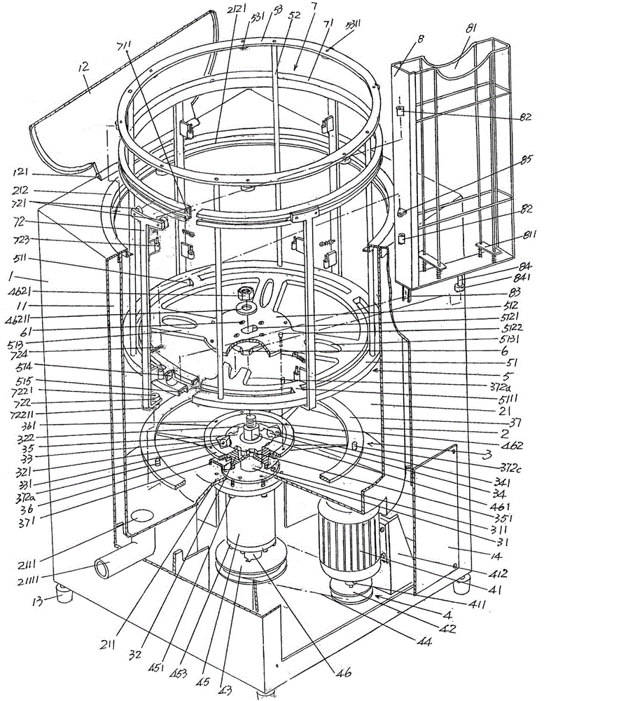
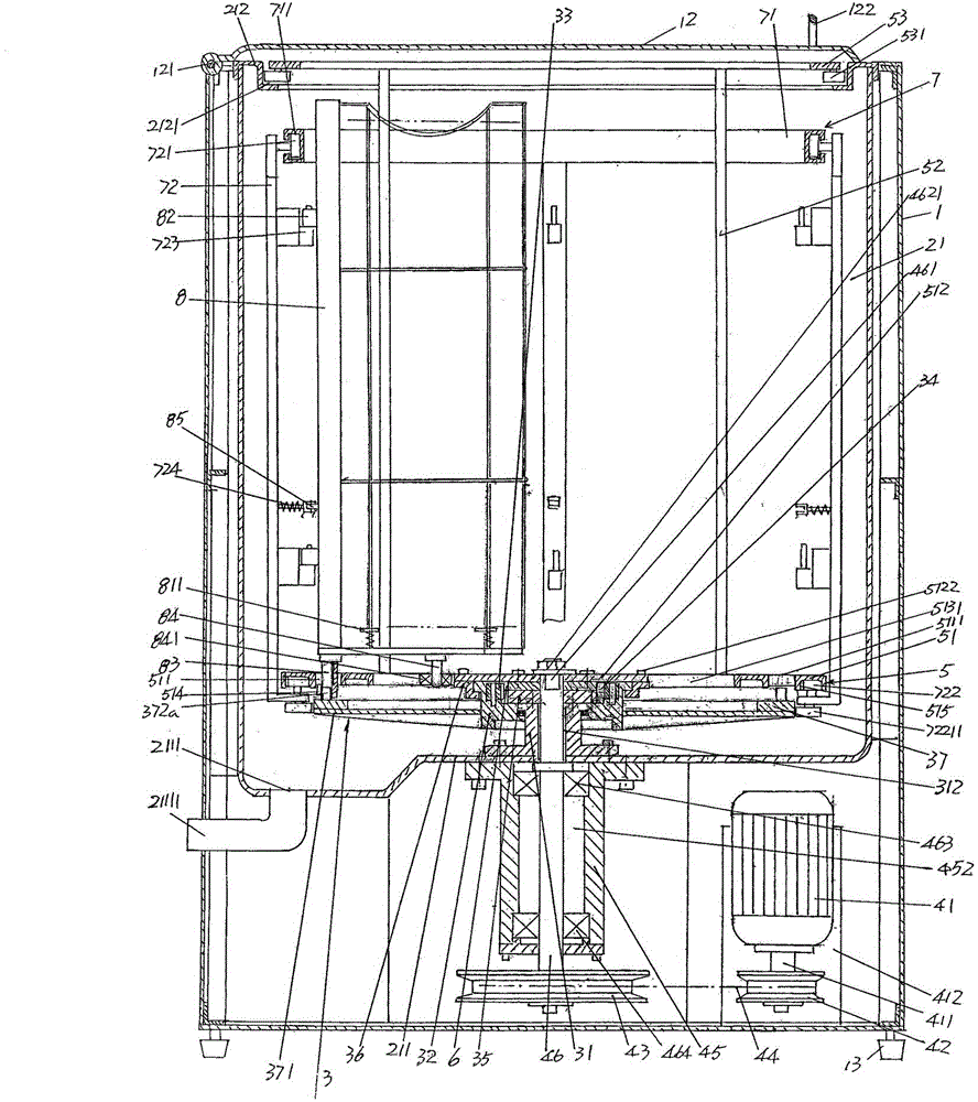
[0025] See figure 1 and figure 2 , a box body 1 and a honey bucket 2 arranged in the box body cavity 11 of the box body 1 are given, and a honey bucket opening and closing cover 12 is pivotally arranged on the upper part of the box body 1 through the pivot shaft 121, by which The opening and closing cover 12 of the honey bucket is used to open or close the upper cavity of the honey bucket cavity 21 of the honey bucket 2 . Preferably, a handle 122 ( figure 2 shown), and a set of box body supporting feet 13 are arranged at the bottom of the aforementioned box body 1. Since the box body 1 in this embodiment is of a rectangular structure, there are at least four box body supporting feet 13, which are d...


PUM


Abstract

The invention discloses a honey extractor, and belongs to the technical field of beekeeping equipment. The honey extractor comprises a tank, a honey accommodating barrel, a honey comb frame overturn mechanism, a power transmission mechanism, a honey comb frame centrifugal rotation mechanism, a cam, a honey comb frame mounting mechanism and a group of honey comb frames; the honey accommodating barrel is arranged in the tank, a honey accommodating barrel opening cover is fittingly arranged on the upper portion of the tank, and honey releasing holes are formed in the bottom wall of a cavity of the honey accommodating barrel; the honey comb frame overturn mechanism is positioned in the cavity of the honey accommodating barrel and is arranged in the center of the bottom wall of the cavity of the honey accommodating barrel; the power transmission mechanism is arranged in a cavity of the tank and corresponds to the lower side of the bottom wall of the cavity of the honey accommodating barrel; the honey comb frame centrifugal rotation mechanism is arranged in the cavity of the honey accommodating barrel and is connected with the power transmission mechanism; the cam is arranged on the honey comb frame centrifugal rotation mechanism; the honey comb frame mounting mechanism is matched with the honey comb frame centrifugal rotation mechanism; the group of honey comb frames is arranged on the honey comb frame mounting mechanism and is matched with the honey comb overturn mechanism and the honey comb frame centrifugal rotation mechanism. The honey extractor has the advantages that an excellent honey extraction effect can be realized, and the yield can be guaranteed; the efficiency can be improved, and the work intensity of beekeepers can be relieved; the operational intensity of the beekeepers can be obviously relieved, and manual overturn operation can be omitted, so that the honey extraction efficiency can be improved.

Description

technical field [0001] The invention belongs to the technical field of beekeeping equipment, in particular to a honey shaker. Background technique [0002] The aforementioned honey shaker is also called a honey throwing machine by beekeepers, which uses centrifugal force to throw out the honey in the honey spleen, and the honeycomb after throwing out the honey is reused. The technical information about the honey shaker can be found in the published Chinese patent documents, typically such as "an electric honey shaker" recommended by the authorization announcement number CN202773730U and "an electric honey shaker" provided by the invention patent application publication number CN103190361A Mechanism”, these two patented schemes not only have the technical effects known in the technical effect column of the description, but also have the advantage of labor-saving operation (electric rather than manual honey shaker). But the technical solutions disclosed in these two patent d...

Claims


Application Information

Patent Timeline
Patent Type & Authority Applications(China)
IPC IPC(8): A01K59/00
Inventor 胡南光
Owner 胡南光
Why Eureka
Try Eureka