Replaceable gun head of multifunctional electric welding gun

An electric welding torch and replaceable technology, which is applied in the direction of arc welding equipment, welding rod characteristics, welding equipment, etc., can solve the problems of high cost, single function, inconvenient use, etc., achieve good effect and simplify the overall structure

Active Publication Date: 2014-02-26
JIANGMEN BOSJOB
View PDF7 Cites 4 Cited by
  • Summary
  • Abstract
  • Description
  • Claims
  • Application Information

AI Technical Summary

Problems solved by technology

The shape of the welding head of the existing drawn-arc welding torch is fixed, and each welding head can only be installed with a corresponding welding material. Generally, a cylindrical or sheet metal block with a matching shape is installed as the welding material. It is relatively simple. When it is necessary to use cylindrical or sheet-shaped molten materials for welding at the same time, two welding t

Method used


Image

  • Replaceable gun head of multifunctional electric welding gun
  • Replaceable gun head of multifunctional electric welding gun
  • Replaceable gun head of multifunctional electric welding gun

Examples


Embodiment 1

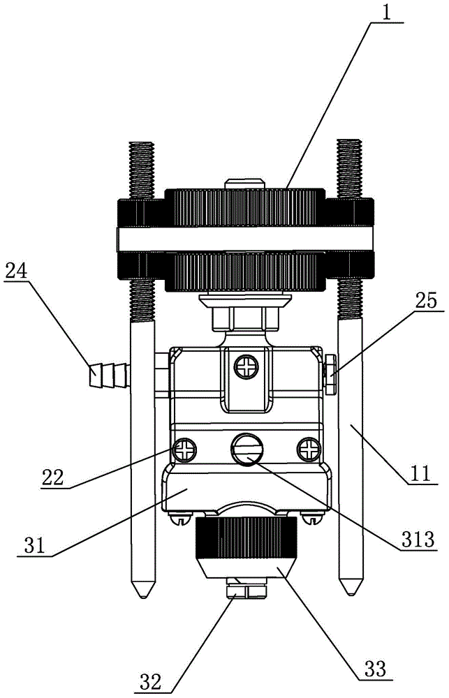
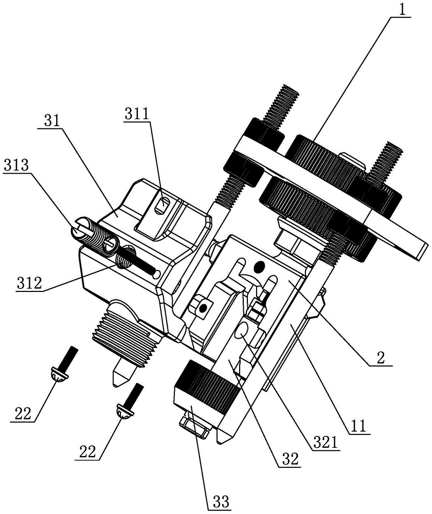
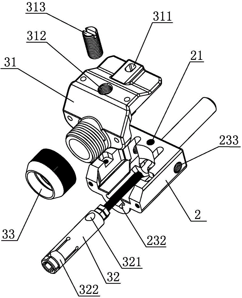
[0027] Reference figure 1 , figure 2 , The multifunctional electric welding gun of the present invention is a schematic structural diagram when a welding column type gun head is used, and includes a connecting piece 1 and a metal conductive piece 2. The conductive piece 2 is connected to the gun body part of the welding gun through the connecting piece 1. 1 is made of insulating material or is electrically isolated from conductive member 2. The conductive member 2 is covered with a cover I 31 made of insulating plastic, and a closed chamber is formed between the cover I 31 and the conductive member 2. A plurality of through holes 311 are provided on the outer cover I 31, and a plurality of screw holes 21 are correspondingly provided on the conductive member 2. The bolts 22 through the through holes 311 are connected to the conductive member 2 so that the outer cover I 31 is fixed on the conductive member 2. The welded object connected with the conductive member 2 protrudes from...

Embodiment 2

[0034] Reference Figure 5 to Figure 7 , The multifunctional electric welding gun of the present invention is a schematic diagram of the structure when the welding blade gun head is used. It includes a connecting piece 1 and a conductive piece 2 that are the same as the first embodiment. The conductive piece 2 is connected to the body part of the welding gun through the connecting piece 1. The connecting member 1 is made of insulating material or is electrically isolated from the conductive member 2 by using an insulating device. The conductive member 2 is covered with a cover II 41 made of insulating plastic, and the cover II 4 is fixed on the conductive member 2 by bolts 22, A closed chamber is formed between the cover II 41 and the conductive member 2. A piece of welded object 42 is set in the installation groove 23 of the conductive member 2, and is pressed by the pressing device 43 to make it close to the conductive member 2, and the front end of the piece of welded object...


PUM


Abstract

The invention discloses a replaceable gun head of a multifunctional electric welding gun. The replaceable gun head comprises an electroconductive member made of metal and an insulated connecting member, a mounting groove is arranged on the electroconductive member, an insulated outer cover is covered above the mounting groove to enable a closed cavity to be formed between the electroconductive member and the outer cover, an opening allowing a fusion welding object connected with the electroconductive member to extend out is arranged at the front end of the cavity, and a welding column fixing member used for fixing a columnar fusion welding object or a compressing device used for compressing a sheet fusion welding object is arranged in the cavity. The columnar fusion welding object or the sheet fusion welding object can be mounted on the replaceable gun head by replacing part of accessories, and the replaceable gun head has various functions and can meet using needs of different using occasions.

Description

Technical field [0001] The invention relates to the field of electric welding equipment, in particular to a replaceable gun head of a multifunctional electric welding gun. Background technique [0002] Pull arc welding is to apply high voltage between the welding head of the electric welding gun and the object to be welded to generate an arc, melt the welded object installed between the welding heads, and weld the object to be welded. The shape of the welding head of the existing drawn-arc electric welding gun is fixed, and each welding head can only be installed with a corresponding welding object. Generally, cylindrical or sheet metal blocks with matching shapes are installed as the welding object. It is relatively simple, and when it is necessary to use column-shaped or sheet-shaped fused materials for welding at the same time, two welding torches are required, and the cost is high. [0003] In addition, the existing drawn-arc electric welding gun generally has the function of ...

Claims


Application Information

Patent Timeline
IPC IPC(8): B23K9/28B23K9/16
CPCB23K9/28B23K9/32B23K9/325
Inventor 翁良轩翁敏翔
Owner JIANGMEN BOSJOB
Why Eureka
Try Eureka