Eureka AIR delivers breakthrough ideas for toughest innovation challenges, trusted by R&D personnel around the world.

Pipeline fixing device for electrical and mechanical equipment

A technology for electromechanical equipment and fixtures, applied in the field of electromechanical equipment pipeline fixtures, can solve problems such as simple supporting devices, chaotic operating platforms, and influence on test results, and achieve the effect of eliminating influence and facilitating processing and operation

Active Publication Date: 2014-02-26
EAST CHINA INST OF OPTOELECTRONICS INTEGRATEDDEVICE
View PDF6 Cites 3 Cited by
  • Summary
  • Abstract
  • Description
  • Claims
  • Application Information

AI Technical Summary

Problems solved by technology

[0002] In the field of mechanical processing, various small-volume, lightweight desktop processing equipment are adopted by more and more users because of their low cost, small footprint, easy installation, and flexibility. Limited, so that the supporting devices of these equipment are relatively simple, such as desktop CMP (chemical polishing) equipment, because of its small space, the air pipe for vacuuming the equipment is directly connected to the grinding head, and there is no fixing in the middle. When grinding, the pipeline will be broken It falls on the grinding disc and affects the grinding process. Due to the involvement of the pipeline on the grinding head, it will also exert additional pulling force on the grinding head, resulting in uneven force on the grinding disc and affecting the grinding quality. Another example is the white light of the British Zego company. Interference test equipment, when testing devices that need to be driven by voltage, because there is no fixing device for the power supply line, during the movement of the test device, the power supply line will form a pulling force on the test piece, which will affect the test results
In practical applications, in order to eliminate such effects, it is often simply and temporarily to tape various pipelines on the equipment platform or build them with some simple temporary devices, resulting in confusion in the operation platform and poor practical effect.

Method used


Image

  • Pipeline fixing device for electrical and mechanical equipment
  • Pipeline fixing device for electrical and mechanical equipment

Examples


Embodiment Construction

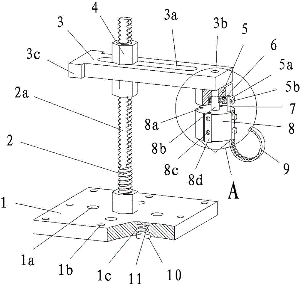
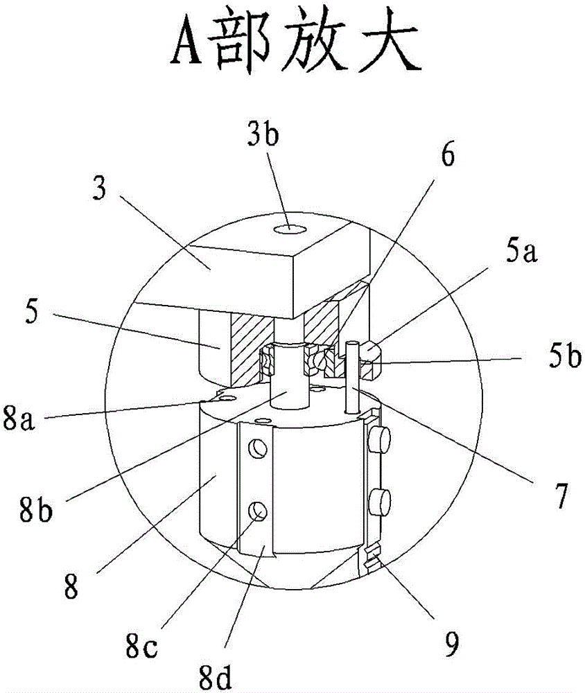
[0015] Such as figure 1 , figure 2 As shown, the electromechanical equipment pipeline fixing device provided by the present invention includes: a base 1, a column 2, a beam 3, a lock nut 4, a rotor seat 5, a rotor 8, and a hook 9. The lower end of the column 2 is connected to the base 1 , the upper side of the column 2 cooperates with the beam 3, and they are fixed and locked by the lock nut 4. The rotor base 5 is connected to one side of the beam 3, and the rotor base 5 is connected with a rotating and matched rotor 8. The rotor 8 is provided with a set of The hook 9 of fixed pipeline.

[0016] A set of fixing holes 1b are provided around the base 1 to fix the base, a set of column screw holes 1a are provided in the middle, and threads are provided on the column, and the lower end of the column 2 is connected with the column screw holes, and the column can be adjusted by connecting with different column screw holes In the working position, the rotating column can adjust th...


PUM


Abstract

A pipeline fixing device for electrical and mechanical equipment is characterized by comprising a base (1), a post (2), a beam (3), a locking nut (4), a rotor seat (5), a fixing pin (7), a rotor (8) and a hook (9). The lower end of the post is connected to the base, the upper side matches with the beam, the locking nut fixes and locks the post and the beam, the rotor seat is fixed on one side of the beam, the rotor matches with the rotor seat, and the hook is connected to the rotor. By means of the technical scheme, the device is simple in structure, the problem of influences caused by unfixed pipelines during machining is solved, and the device has the advantages of convenience for machining and operating, improvement on operating efficiency and the like.

Description

Technical field: [0001] The invention relates to a processing auxiliary device, in particular to a pipeline fixing device for electromechanical equipment. Background technique: [0002] In the field of mechanical processing, various small-volume, lightweight desktop processing equipment are adopted by more and more users because of their low cost, small footprint, easy installation, and flexibility. Limited, so that the supporting devices of these equipment are relatively simple, such as desktop CMP (chemical polishing) equipment, because of its small space, the air pipe for vacuuming the equipment is directly connected to the grinding head, and there is no fixing in the middle. When grinding, the pipeline will be broken It falls on the grinding disc and affects the grinding process. Due to the involvement of the pipeline on the grinding head, it will also exert additional pulling force on the grinding head, resulting in uneven force on the grinding disc and affecting the g...

Claims


Application Information

Patent Timeline
Patent Type & Authority Applications(China)
IPC IPC(8): B24B37/34
CPCF16L3/06F16L3/16H02G3/04
Inventor 庄须叶郭群英吕东锋展明浩黄斌陈博陈璞何凯旋刘磊王鹏王文婧汪祖民徐栋
Owner EAST CHINA INST OF OPTOELECTRONICS INTEGRATEDDEVICE
Why Eureka
Eureka Blog
Learn More