Plant cooling system

A cooling system and factory technology, applied in the system field, can solve the problems of poor cooling effect and large power consumption, and achieve the effect of simple structure, reasonable design and water saving.

Inactive Publication Date: 2014-02-26
余姚市士森铜材厂
View PDF0 Cites 3 Cited by
  • Summary
  • Abstract
  • Description
  • Claims
  • Application Information

AI Technical Summary

Problems solved by technology

[0002] With the development of industrialization, factories have become a concentrated place for the production of various items for people. At present, most factories have production lines composed of large machines or equipment, and the factory buildings basically use large-scale assembled frame buildings. The roof of the factory building It is made of iron sheets, and the temperature inside such a factory building is very high in summer, which is a kind of torment for the workers. At present, there are many cooling systems in the factory building, such as fans, which have poor cooling effect and use air conditioners. This cooling method consumes a lot of power

Method used


Image

  • Plant cooling system

Examples


Embodiment Construction

[0010] In order to make the objectives, technical solutions and advantages of the present invention clearer, the following further describes the present invention in detail with reference to the accompanying drawings and embodiments. It should be understood that the specific embodiments described herein are only used to explain the present invention, but not to limit the present invention.

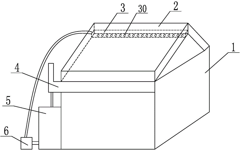
[0011] See figure 1 , figure 1 It is a schematic diagram of the structure of the present invention.

[0012] A cooling system for a factory, comprising a plant body 1, a roof plate 2, the roof plate 2 is a thin-walled rectangular parallelepiped structure, and a water outlet pipe 3 is provided on the upper side of the interior of the roof plate 2. In summer, the water outlet pipe 3 is used The temperature of the roof board 2 is lowered, so that the effect of cooling the plant can be effectively achieved. The water outlet pipe 3 is evenly provided with a plurality of water outlet holes 30, the...


PUM


Abstract

The invention relates to a plant cooling system which comprises a plant body and a roof plate. The roof plate is of a thin-wall cuboid structure. A water outlet pipe is arranged on the upper side in the roof plate. A plurality of water outlets are evenly formed in the water outlet pipe. A water collecting pipe is arranged on the lower side of the roof plate. The water collecting pipe is connected with a water storage box through a water discharging pipe. The water storage box is connected with a water pump which is connected with the water outlet pipe through a water conveying pipe. The plant cooling system is simple in structure and reasonable in design, the water outlet pipe is arranged in the roof plate, the water outlet pipe is used for cooling the roof plate in summer, accordingly, the effect of plant cooling can be effectively achieved, the water collecting pipe and the water storage box are arranged so that water flows down from the roof plate can be effectively collected, therefore, water resources are saved, and the water pump is arranged so that circulating working of the cooling system can be achieved.

Description

Technical field [0001] The invention relates to a system, in particular to a factory cooling system. Background technique [0002] With the development of industrialization, factories have become a kind of centralized place for the production of various goods for people. At present, most factories have production lines composed of large machines or equipment, and the factory buildings basically adopt large-scale assembled frame houses and the roofs of the factories. It is made of iron sheets. The temperature inside such a factory building is very high in summer, which is a torment for workers. At present, there are also many factory cooling systems, such as fans. This cooling method has poor cooling effect and uses air conditioning. This cooling method consumes a lot of power. To solve the above problems, a new technical solution is provided. Summary of the invention [0003] The purpose of the present invention is to overcome the shortcomings of the prior art and provide a fact...

Claims


Application Information

Patent Timeline
IPC IPC(8): E04H5/02F24F5/00
CPCY02P80/10
Inventor 毛秧群
Owner 余姚市士森铜材厂
Why Eureka
Try Eureka