Novel mixed-flow pump

A mixed-flow pump, a new type of technology, applied in the direction of pumps, pump components, and components of pumping devices for elastic fluids, etc., can solve the problems of insignificant use effect and complex structure, improve water inlet conditions, and reduce cavitation. Effects of Noise, Suppression Strength, and Range

Inactive Publication Date: 2014-02-26
谭国华
View PDF0 Cites 2 Cited by
  • Summary
  • Abstract
  • Description
  • Claims
  • Application Information

AI Technical Summary

Problems solved by technology

This structure is relatively complicated, and the effect of using it is not obvious

Method used


Image

  • Novel mixed-flow pump
  • Novel mixed-flow pump

Examples


Embodiment Construction

[0012] In order to further understand and recognize the structure, features and effects of the present invention, a preferred embodiment is now given, and detailed descriptions are as follows in conjunction with the accompanying drawings:

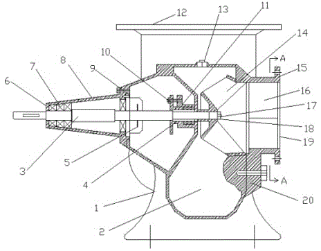
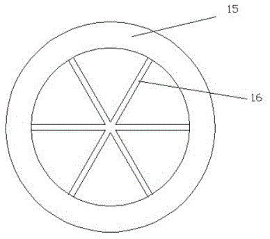
[0013] Such as figure 1 with figure 2 As shown, the novel mixed-flow pump described in this embodiment mainly includes a pump body 1, a pump shaft 3, an impeller 14, and an impeller 16. On one end of the pump shaft 3, the impeller 14 is installed through the pump shaft 3 in the mixed flow chamber 2 composed of the pump body 1 and the pump cover 10. Into an integral structure, the side wall of the pump body 1 is provided with a suction port 19, the upper part of the pump body 1 is provided with a water outlet 12, and the suction port 19, the mixed flow chamber 2 and the water outlet 12 are connected. The left side wall of the pump body 1 is provided with The bearing body 8 fixed with it, the pump shaft 3 extends out of the bearing body 8;...


PUM


Abstract

The invention discloses a novel mixed-flow pump which comprises a pump body, a pump shaft, an impeller and rotating resistance blades. The pump shaft is mounted and supported in the pump body through a bearing body, a bearing, a front cover, a rear cover and a shaft sleeve. The impeller is fixed at one end of the pump shaft, the rotating resistance blades are arranged at the front end of a pump cover, and the rotating resistance blades and the pump cover are cast to be of an integral structure. The impeller is arranged in a mixed-flow chamber, a water outlet is formed in the upper portion of the pump body, and a sucking opening, the mixed-flow chamber and the water outlet are communicated. According to the novel mixed-flow pump, the rotating resistance blades are evenly arranged on the pump cover of an existing mixed-flow pump, the pressure fluctuation and the cavitation noise of water flow are lowered, the water inlet condition of a water pump is improved, and the safety and the stability of operation of the water pump are improved.

Description

technical field [0001] The invention relates to a pump, in particular to a novel mixed-flow pump. Background technique [0002] The structure and performance of the mixed flow pump are between the axial flow pump and the centrifugal pump. It is an ideal pump type that absorbs the advantages of the centrifugal pump and the axial flow pump and compensates for the shortcomings of the two aspects. At present, the hydraulic design of mixed-flow pumps mostly adopts the design method of centrifugal pumps, that is, the velocity coefficient method. Cylindrical blades or twisted blades are used, which have strong flow capacity. However, if sewage pumping stations are used, the water quality is complex and there is much sediment. A lot of sundries will easily cause the impeller blades to be entangled with sundries, blockage, deformation of the outer end mechanical seal, failure of the mechanical seal, water ingress to the motor, frequent alarms of the pump, increased maintenance times,...

Claims


Application Information

Patent Timeline
Patent Type & Authority Applications(China)
IPC IPC(8): F04D11/00F04D29/66
Inventor 谭国华
Owner 谭国华
Why Eureka
Try Eureka