
Multiplexing/demultiplexing optical equipment and method for realizing optical path multiplexing/demultiplexing

An optical device and demultiplexing technology, applied in the field of wavelength division multiplexing/demultiplexing, which can solve the problems of small constant distance and poor practicability of multiplexing/demultiplexing optical devices.

Active Publication Date: 2014-02-26
HISENSE BROADBAND MULTIMEDIA TECH
View PDF5 Cites 4 Cited by
  • Summary
  • Abstract
  • Description
  • Claims
  • Application Information

AI Technical Summary

Problems solved by technology

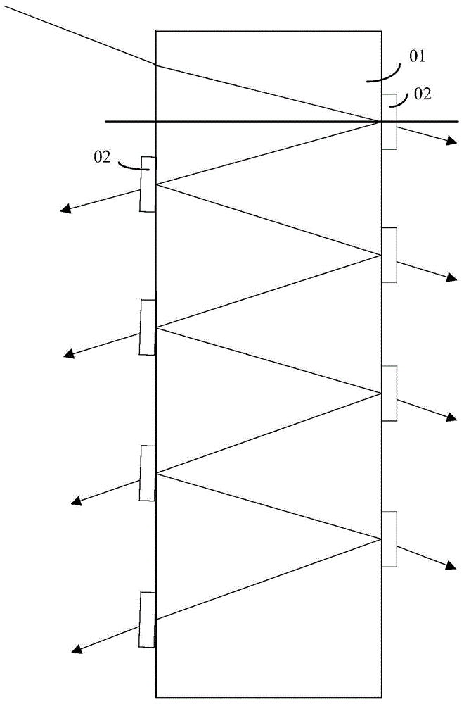
[0009] It can be seen from the above that in the existing multiplexing / demultiplexing optical equipment, two groups of parallel selective wavelength filters are arranged in the double-sided parallel optical block, and the interval between the two parallel groups of selective wavelength filters is preset Due to the need to set the selective wavelength filter in the constant distance, and the required constant distance is small, it is easy to make the selective wavelength filter set in the double-sided parallel optical block interfere with each other, resulting in Less practical for multiplexing / demultiplexing optics

Method used


Image

  • Multiplexing/demultiplexing optical equipment and method for realizing optical path multiplexing/demultiplexing
  • Multiplexing/demultiplexing optical equipment and method for realizing optical path multiplexing/demultiplexing
  • Multiplexing/demultiplexing optical equipment and method for realizing optical path multiplexing/demultiplexing

Examples


Embodiment Construction

[0067] The technical solutions of the various embodiments of the present invention will be clearly and completely described below in conjunction with the accompanying drawings. Apparently, the described embodiments are only some of the embodiments of the present invention, not all of them. Based on the embodiments of the present invention, all other embodiments obtained by persons of ordinary skill in the art without making creative efforts belong to the protection scope of the present invention.

[0068] In the existing multiplexing / demultiplexing optical equipment, two groups of parallel selective wavelength filters are arranged in the double-sided parallel optical block, and the interval between the two parallel groups of selective wavelength filters is a preset constant distance, Due to the small constant distance required, it is easy to make the selective wavelength filters arranged in the double-sided parallel optical block interfere with each other, resulting in poor pra...


PUM


Abstract

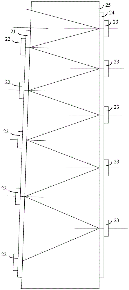
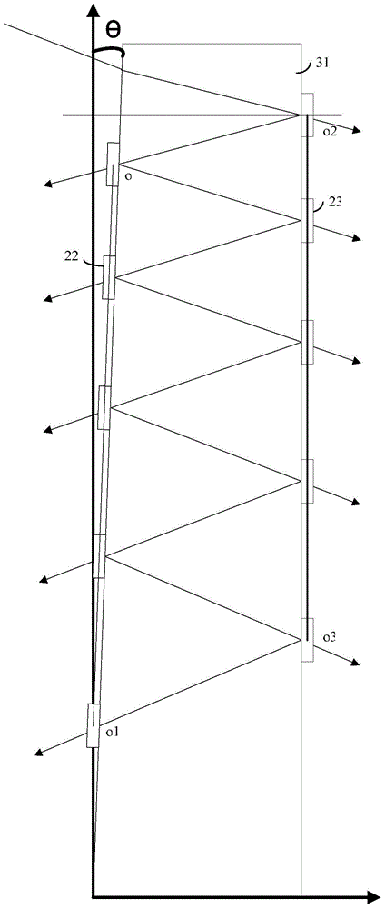
The invention discloses multiplexing / demultiplexing optical equipment and a method for realizing optical path multiplexing / demultiplexing. According to the multiplexing / demultiplexing optical equipment, a first wedge-shaped optical block is fixed on a first side surface of a dielectric body, a second wedge-shaped optical block is fixed on a second side surface opposite to the first side surface on the dielectric body, and the first side surface and the second side surface form a preset angle; an incidence port is formed in the upper part of the side surface of the first wedge-shaped optical block; one or more parallel selective-wavelength filters are fixed below the incidence port along the vertical direction of the first wedge-shaped optical block, and the connection line of the center of each selective-wavelength filter is a straight line and is parallel to the first side surface; one or more parallel selective-wavelength filters are fixed along the vertical direction of the second wedge-shaped optical block, and the connection line of the center of each selective-wavelength filter is a straight line and is parallel to the second side surface. By applying the multiplexing / demultiplexing optical equipment and the method disclosed by the invention, the practicability of the multiplexing / demultiplexing optical equipment can be improved.

Description

technical field [0001] The invention relates to wavelength division multiplexing / demultiplexing technology, in particular to a multiplexing / demultiplexing optical device and a method for realizing optical path multiplexing / demultiplexing. Background technique [0002] Wavelength division multiplexing (WDM, Wave-length Division Multiplexing) is to combine two or more optical carrier signals of different wavelengths at the sending end through a multiplexer (Multiplexer), and couple the combined optical carrier signals to the optical line. In the technology of transmission in the same optical fiber, optical carrier signals of different wavelengths carry different information; at the receiving end, the demultiplexer (Demultiplexer) separates the coupled optical carrier signals of various wavelengths to separate out different wavelengths The optical carrier signal is then output to the optical receiver, which is further processed by the optical receiver to restore the original si...

Claims


Application Information

Patent Timeline
Patent Type & Authority Applications(China)
IPC IPC(8): G02B6/293
Inventor 王彬
Owner HISENSE BROADBAND MULTIMEDIA TECH
Learn More