
Design method of furnace roll profile in furnace section of continuous annealing unit

A continuous annealing unit and roll shape design technology, applied in the field of metallurgical steel rolling, can solve problems such as roll shape optimization and qualitative analysis of unfurnished rolls

Inactive Publication Date: 2016-05-04
唐山扬邦钢铁技术研究院有限公司
View PDF2 Cites 2 Cited by
  • Summary
  • Abstract
  • Description
  • Claims
  • Application Information

AI Technical Summary

Problems solved by technology

However, so far, scholars at home and abroad have only stayed at the stage of qualitative analysis on the influence of roll shape factors on the "deviation" and "bending" of the strip.
No literature has been retrieved about the establishment of a mathematical model from the mechanical point of view to quantitatively study the influence of roll shape factors on strip "deviation" and "bow". Studies on the optimization of roll profile are found in the literature

Method used


Image

  • Design method of furnace roll profile in furnace section of continuous annealing unit
  • Design method of furnace roll profile in furnace section of continuous annealing unit
  • Design method of furnace roll profile in furnace section of continuous annealing unit

Examples


Embodiment 1

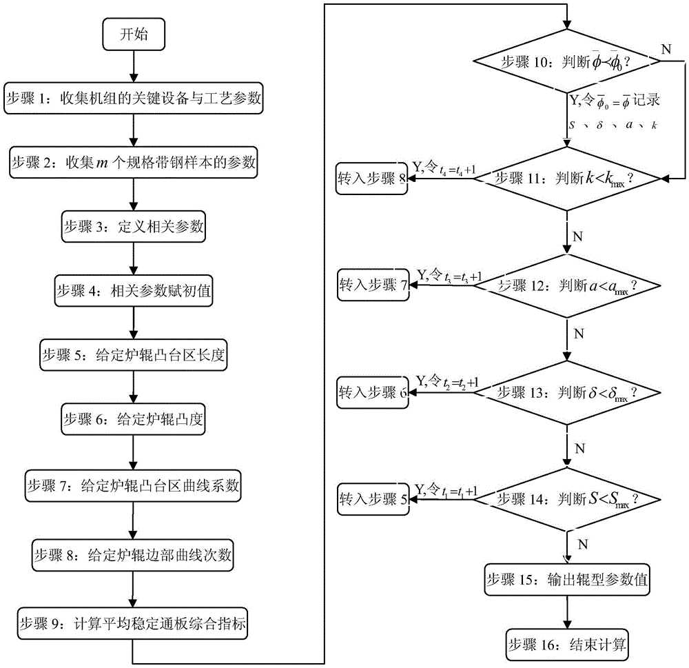
[0050] exist figure 1 In the general flowchart of the design method of the furnace roll profile of the continuous annealing unit shown, first, in step 1, collect the profile parameters of the furnace roll, mainly including: the maximum roll diameter of the furnace roll D=900mm, the length of the furnace roll body L =1950mm, furnace roller surface roughness Ra r1 =4.5μm;

[0051] Subsequently, in step 2, the process parameters of this process section are collected, mainly including: the set tension σ=6.5MPa, the set temperature T=750°C of the process section, and the indoor temperature T under normal conditions sw =25℃;

[0052] Subsequently, in step 3, heat transfer related parameters are collected, mainly including: furnace roll and strip heat transfer coefficient a 1 =2500W / m 2 ·℃, furnace roller and gas heat transfer coefficient a 2 =α B =50W / m 2 ·℃, furnace roller specific heat C p =460J / kg·℃, furnace roller thermal expansion coefficient β=12×10 -6 / °C, furnace ro...

Embodiment 2

[0083] First, in step 1, collect the roll shape parameters of the furnace roll, which mainly include: the maximum roll diameter of the furnace roll D=900mm, the length of the roll body of the furnace roll L=1950mm, the surface roughness of the furnace roll Ra r1 =1.8μm;

[0084] Subsequently, in step 2, the process parameters of this process section are collected, mainly including: the set tension of the process section σ=7.3MPa, the set temperature T=720℃, the indoor temperature T under normal conditions sw =25℃;

[0085] Then, in step 3, the related parameters of heat transfer are collected, mainly including: heat transfer coefficient a between furnace roll and strip steel 1 =2500W / m 2 °C, heat transfer coefficient a between furnace roll and gas 2 =α B =50W / m 2 °C, specific heat of furnace roll C p =460J / kg·℃, thermal expansion coefficient of furnace roll β=12×10 -6 / ℃, thermal conductivity of furnace roll K=29W / m·℃ and furnace roll density ρ=7800kg / m 3 Wait.

[008...


PUM


Abstract

A design method of an annealing unit furnace section furnace roll shape includes steps, executed through a computer, of 1, collecting key equipment and process parameters of an unit; 2, collecting parameters of m specification strip steel samples; 3, defining relevant parameters; 4, giving initial values for the relevant parameters; 5, allowing the furnace roll boss length S to be that S = Smin + t1*Delta S; 6, allowing the furnace roll convexity delta to be that delta = delta min + t2*Delta delta; 7, allowing the furnace roll boss curve coefficient a to be that a = amin + t3 * Delta a; 8, allowing the furnace edge curve number k to be that k = kmin + t4 * Delta k; 9, calculating an average stable passing composite indicator of the m specification strip steel samples; 10, judging whether k < kmax, a < amax, delta < delta max, S < Smax are satisfied or not; 11, outputting the roll shape parameters S, delta,a and k. By the aid of the method, the strip steel is prevented from deviation and buckling, and optimal effect on stability and passing performance of conventional incoming strip steel is achieved.

Description

technical field [0001] The invention belongs to the technical field of metallurgical steel rolling, and in particular relates to a design method for a furnace roll profile of a continuous annealing unit. Background technique [0002] In the process of continuous annealing production, the high-speed and stable passability of strip steel is often double tested by two defects: "deviation" and "bending". The so-called "deviation" defect refers to the phenomenon that the strip deviates from the center of the production line and moves to one side of the roller during the operation of the continuous annealing furnace; The uneven lateral force on the steel produces a slab surface with oblique folds. After the defects occur, strip breakage accidents often occur, which not only affects the production efficiency, but even causes the product to be downgraded or judged to be scrapped, which brings great economic losses to the enterprise. Therefore, in order to avoid the deviation of th...

Claims


Application Information

Patent Timeline
IPC IPC(8): G06F17/50C21D9/56
Inventor 白振华王瑞王凯朱厚鸿任亚超兴百宪骆国玲
Owner 唐山扬邦钢铁技术研究院有限公司
Learn More